SV-COM-X83 Installation and Configuration
17-14 SkyView System Installation Guide - Revision AA
o Shield of the cable from SV-COM-T8 #1 Pins 1 and 2
o SV-COM-T8 #1 Pin 9
o Shield of the cable from SV-COM-T8 #1 Pins 23 and 9
o SV-COM-T8 #2 Pin 1
o Shield of the cable from SV-COM-T8 #2 Pins 1 and 2
o SV-COM-T8 #2 Pin 9
o Shield of the cable from SV-COM-T8 #2 Pins 23 and 9
Rather than trying to terminate these eight connections directly to SV-INTERCOM-2S Pin 1, we
suggest connecting a wire to Pin 1, then bond all nine connections together. One method is to
tie-wrap the bundle of wires and shields together, twist the wires together, and solder the nine
wires and shields. After the solder cools, use heat shrink tubing to insulate the connection. The
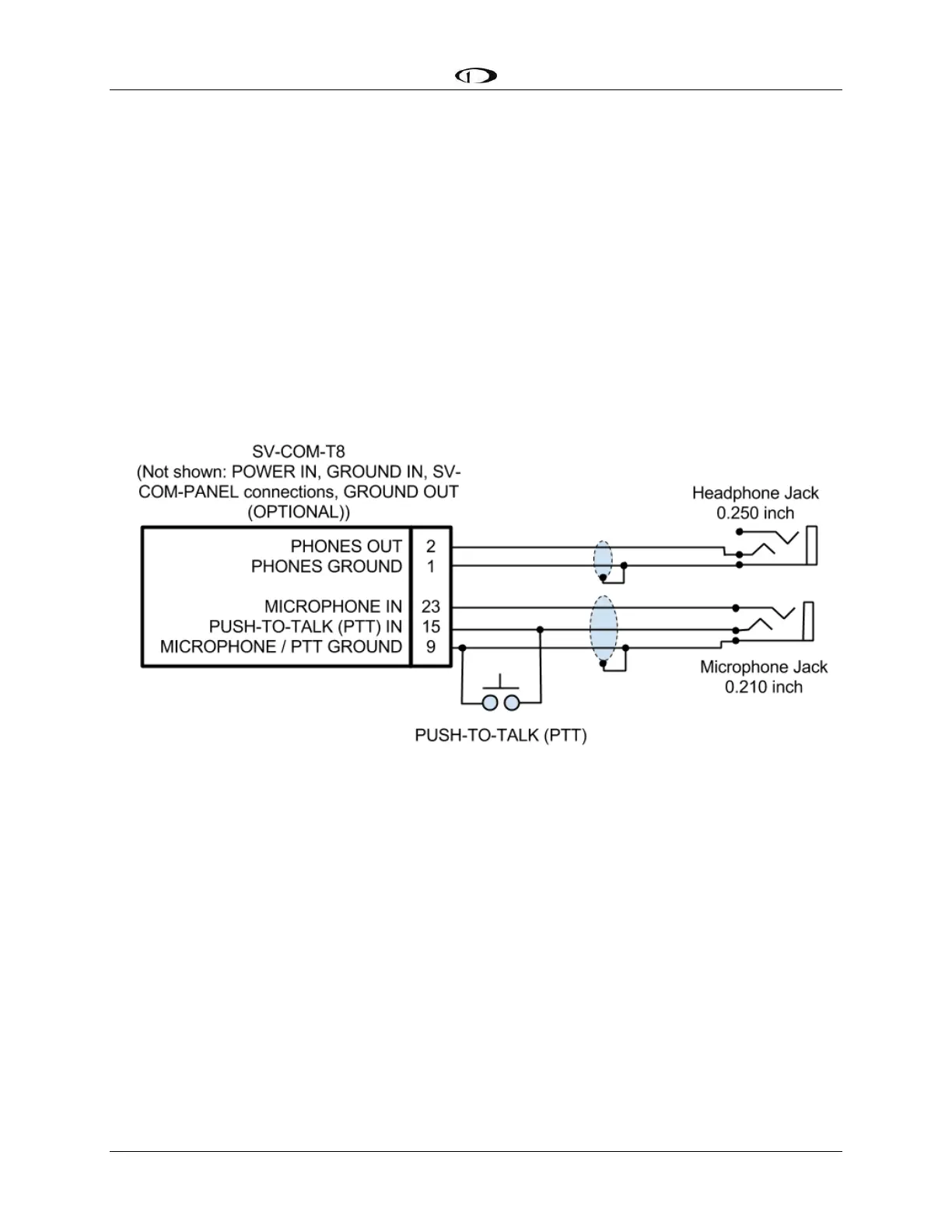
following figure depicts connecting a SV-COM-T8 directly to a single headset (headphone +
microphone) and a Push-To-Talk Switch when no intercom is used in a single-place aircraft.
Figure 190 – SV-COM-T8 to Headset