SV-AP-PANEL Installation
SkyView System Installation Guide - Revision AA 18-5
Trim and Flaps Position Potentiometers in the SV-EMS-220/221 Installation and Configuration
section.
Trim Motor Control Safety Features
Pilot trim controls override Copilot trim controls.
If SkyView Network connection or SkyView power is lost, the trim motor functions will
continue to function as long as avionics power is available at Pin 9. When SkyView is not
powered on (not communicating with the SV-AP-PANEL) the speed scheduling features
(QUICKEST TRIM SPEED / SLOWEST TRIM SPEED) are not available. In this failsafe mode,
the trim motors will run at their full speed when trim buttons are pushed.
If a trim control button is detected as pushed when power is first applied to Pin 9, trim
control will not activate until the button is first released.
If a trim control button is pushed for more than five seconds (or longer, such as a stuck
button), trim control on that axis will be temporarily inactivated until the button is first
released.
Motor outputs are protected against short circuits.
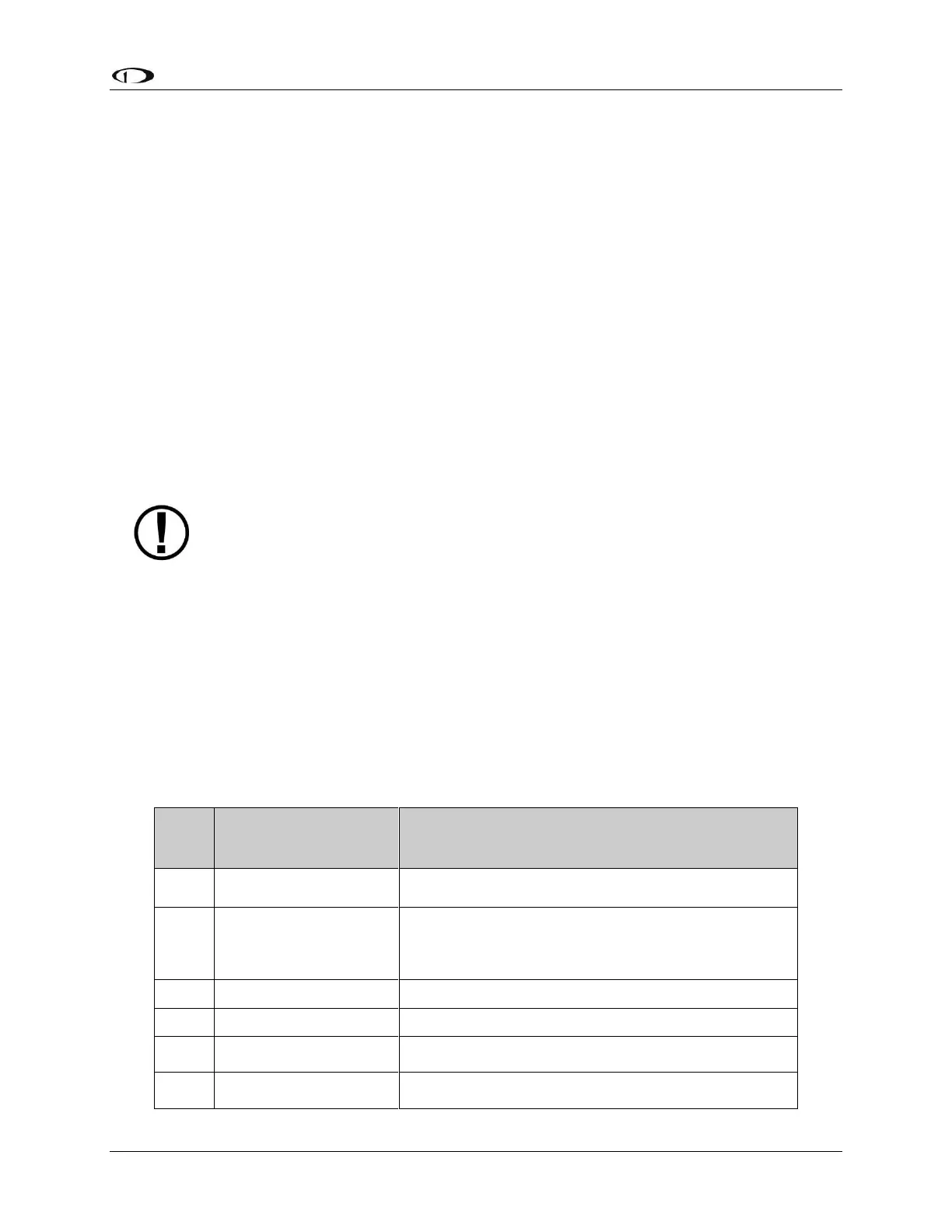
If two SV-AP-PANELs are installed, connect only one SV-AP-PANEL to control trim
motors. Do not connect the second SV-AP-PANEL’s D15M connector in parallel
with the first SV-AP-PANEL’s D15M connector – doing so could cause unexpected
behaviour and/or damage to the units and the trim motors.
On the D15M connector, Power (Pin 9) and Ground (Pin 2) connections are only required to
control a Pitch trim motor and/or a Roll trim motor. If the trim motor outputs are not used,
Power (Pin 9) and Ground (Pin 2) should not be connected.
Ray Allen trim motors are known to work - connect the white wires to Pins 7 and 8 (MOTOR 1)
and/or Pins 14 and 15 (MOTOR 2). If using other trim motors, ensure that the trim motor’s
maximum current does not exceed 2A.
The functions assigned to each pin in Table 98 below reflect Motor 1 being used for TRIM
UP/DOWN and Motor 2 being used for TRIM RIGHT/LEFT.
This pin is not used, do
not connect.
This pin is not used, do not connect.
Aircraft Electrical Ground
If trim motor(s) control is not used, do not connect. Power
and ground for the SV-AP-PANEL front panel buttons is
provided by SkyView Network.
Motor 1: Pin 7 polarity is +, Pin 8 polarity is -
Motor 1: Pin 7 polarity is -, Pin 8 polarity is +
Motor 1: Pin 7 polarity is +, Pin 8 polarity is -
Motor 1: Pin 7 polarity is -, Pin 8 polarity is +