Appendix C: Wiring and Electrical Connections
SkyView System Installation Guide - Revision AA 23-15
(determined by
installer)
Pins 12/13 are the same TX signal. Provided for
convenience when connecting multiple ARINC
receivers.
(determined by
installer)
Pins 12/13 are the same TX signal. Provided for
convenience when connecting multiple ARINC
receivers.
(determined by installer)
(determined by installer)
(determined by
installer)
Pins 24/25 are the same TX signal. Provided for
convenience when connecting multiple ARINC
receivers.
(determined by
installer)
Pins 24/25 are the same TX signal. Provided for
convenience when connecting multiple ARINC
receivers.
Table 119 – SV-ARINC-429 D25F Connector
SV-ADSB-470 Pinout (SV-HARNESS-ADSB)
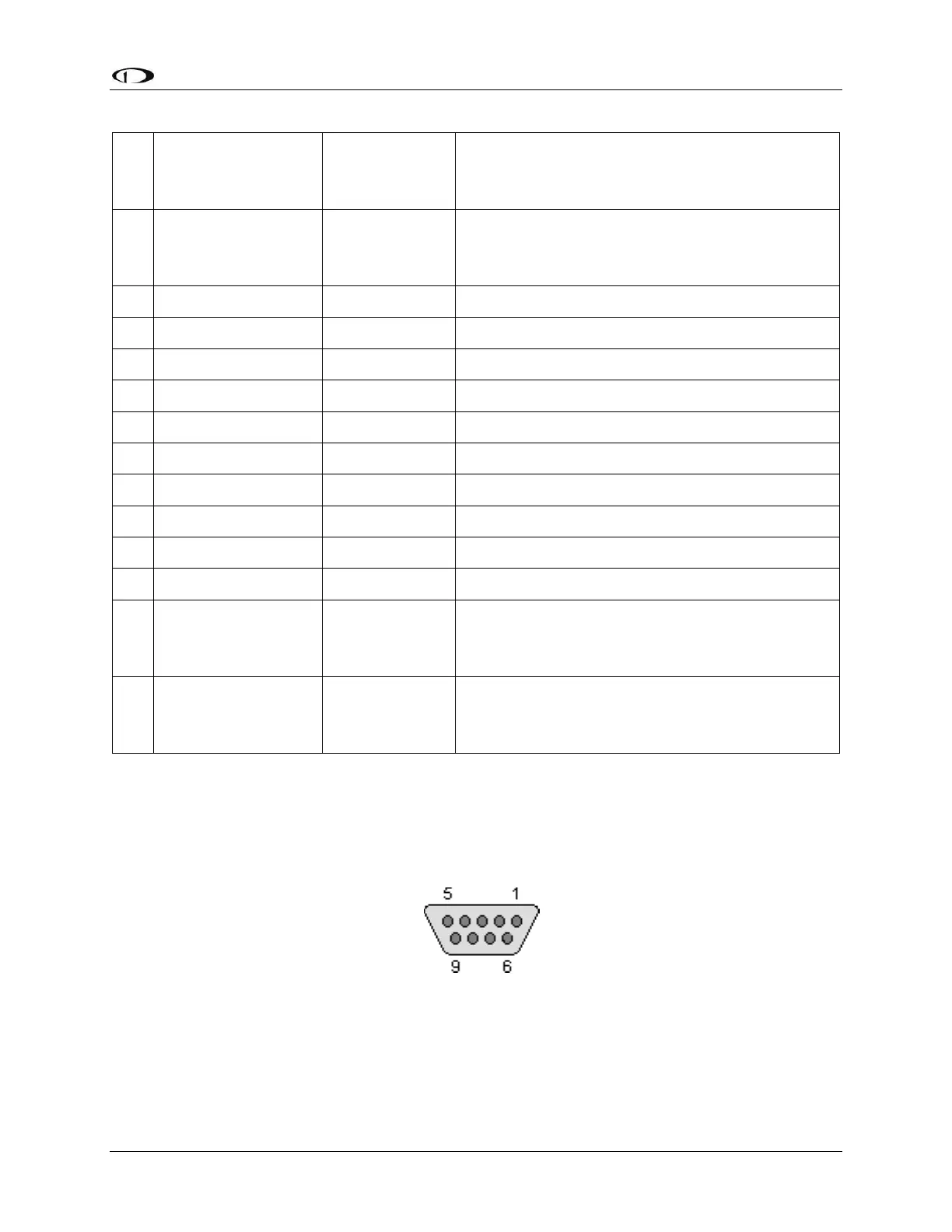
Figure 222 - SV-ADSB-470 D9M Connector Pin Numbering
The SV-ADSB-470 uses a D9F connector (included with the SV-NET-ADSB harness). Figure 222
above shows pin numbering for the mating D9M connector, installed on the SV-HARNESS-ADSB,
from the rear (pin insertion) view.