SV-EMS-220 Engine Monitoring System Installation and Configuration
SkyView HDX System Installation Manual - Revision E 10-31
o ENABLE YES
o COLOR RED
o TOP 15.0 VOLTS
o BOTTOM 14.6 VOLTS
10.7.5 Example Contact Sensor Setup
Assume this sensor was mapped on the Sensor Input Mapping Wizard as:
Table 22: Example Sensor Input Mapping for C37 P9 (as a Contact)
Now, we want to configure its alert and graphical properties. Go to the Sensor Setup
Menu and open the CANOPY CONTACT Page (SETUP MENU > EMS SETUP >
SENSOR SETUP > CANOPY CONTACT).
Note that although inputs set up as contacts can physically accept up to 15V
(so that they can accept nominal aircraft voltage as one (1) of their two (2)
states), and up 30V DC as a brief surge, without damaging the input.
However, the maximum the EMS can measure is 5.0V. This means that as
depicted below, the two (2) measured ranges should be set to 0-2.5V and
2.5-5V to measure the absence and presence of power.
Canopy Contact is a special case input. If a configuration file is loaded
containing:
canopy_warn_rpm=XXXX (where that's something between 0 and 9999)
then the audio warning “Check Canopy Latch” will play if the engine RPM
exceeds the specified RPM level and the canopy input is in the open state.
One (1) may generate a .dfg file with only this line, place it on an USB flash
drive and load it in SETUP MENU > SYSTEM SOFTWARE > LOAD FILES.
Configure CANOPY CONTACT with the following properties:
• ALARM: OFF
• MAXIMUM GRAPHICAL DISPLAY:5.0 VOLTS
• MINIMUM GRAPHICAL DISPLAY:0.0 VOLTS
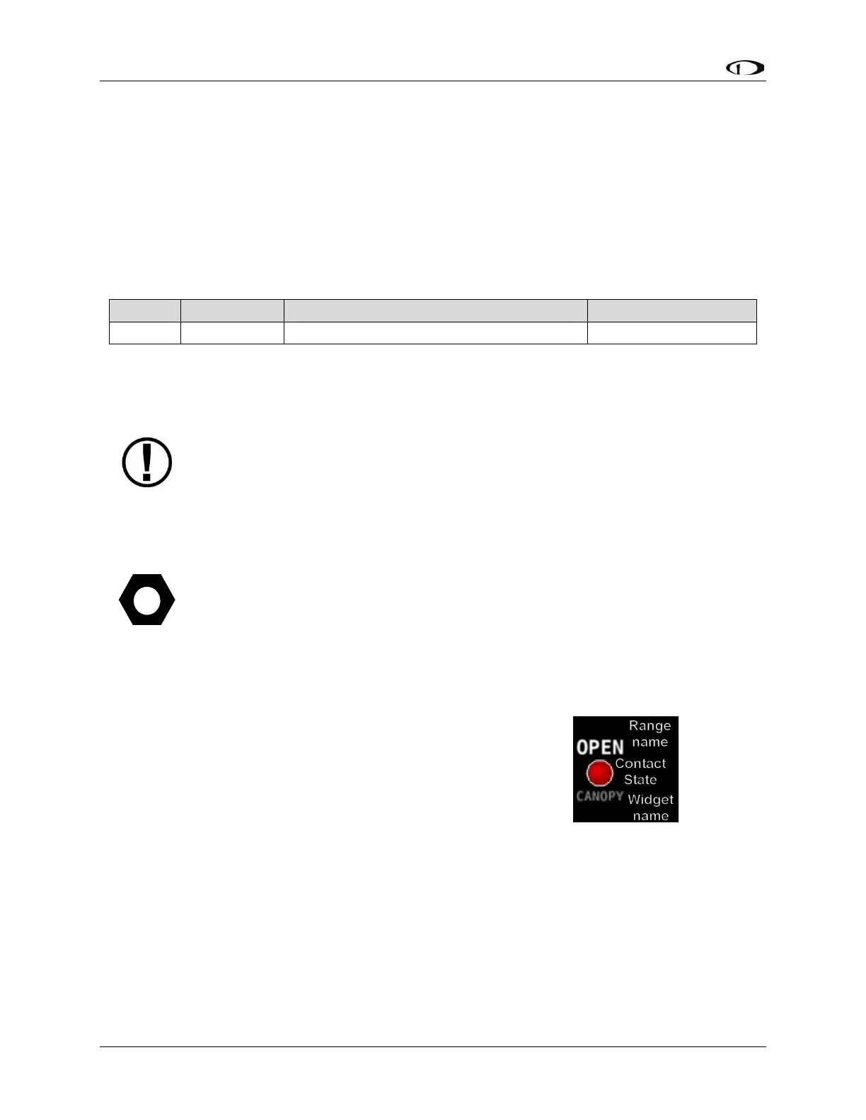
• RANGE 1
o ENABLE YES
o NAME OPEN
o COLOR RED
o TOP 5.0 VOLTS
o BOTTOM 2.5 VOLTS
• RANGE 2
o ENABLE YES
Figure 60: