SV-EMS-220 Engine Monitoring System Installation and Configuration
SkyView HDX System Installation Manual - Revision E 10-33
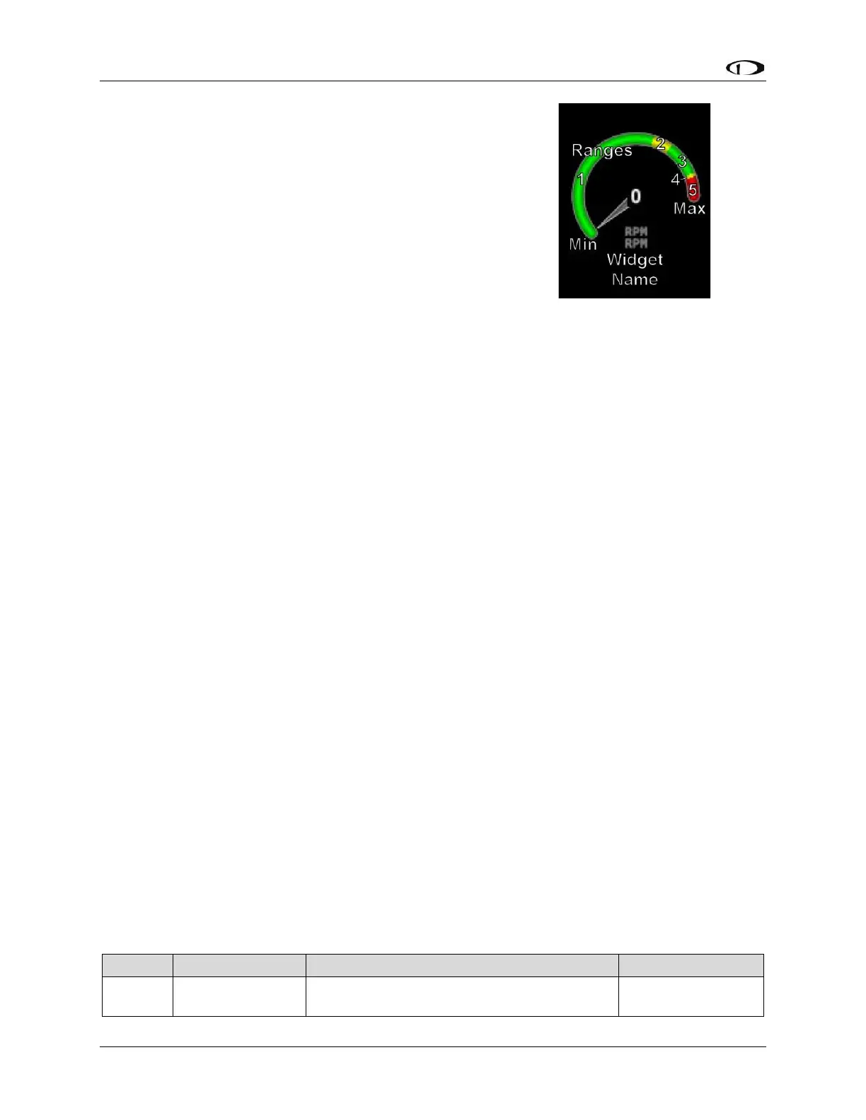
• MINIMUM GRAPHICAL DISPLAY:0 RPM
• SHOW SENSOR UNITS YES
• RANGE 1
o ENABLE YES
o COLOR GREEN
o TOP 2000 RPM
o BOTTOM 0 RPM
• RANGE 2
o ENABLE YES
o COLOR YELLOW
o TOP 2250 RPM
o BOTTOM 2000 RPM
• RANGE 3
o ENABLE YES
o COLOR GREEN
o TOP 2700 RPM
o BOTTOM 2250 RPM
• RANGE 4
o ENABLE YES
o COLOR YELLOW
o TOP 2750 RPM
o BOTTOM 2700 RPM
• RANGE 5
o ENABLE YES
o COLOR RED
o TOP 3000 RPM
o BOTTOM 2750 RPM
10.7.7 Example Oil Temperature Sensor Setup
Assume this sensor was mapped on the Sensor Input Mapping Wizard as:
Table 24: Example Sensor Input Mapping for C37 P7 (Oil Temp)