System Overview
SkyView HDX System Installation Manual - Revision E 2-15
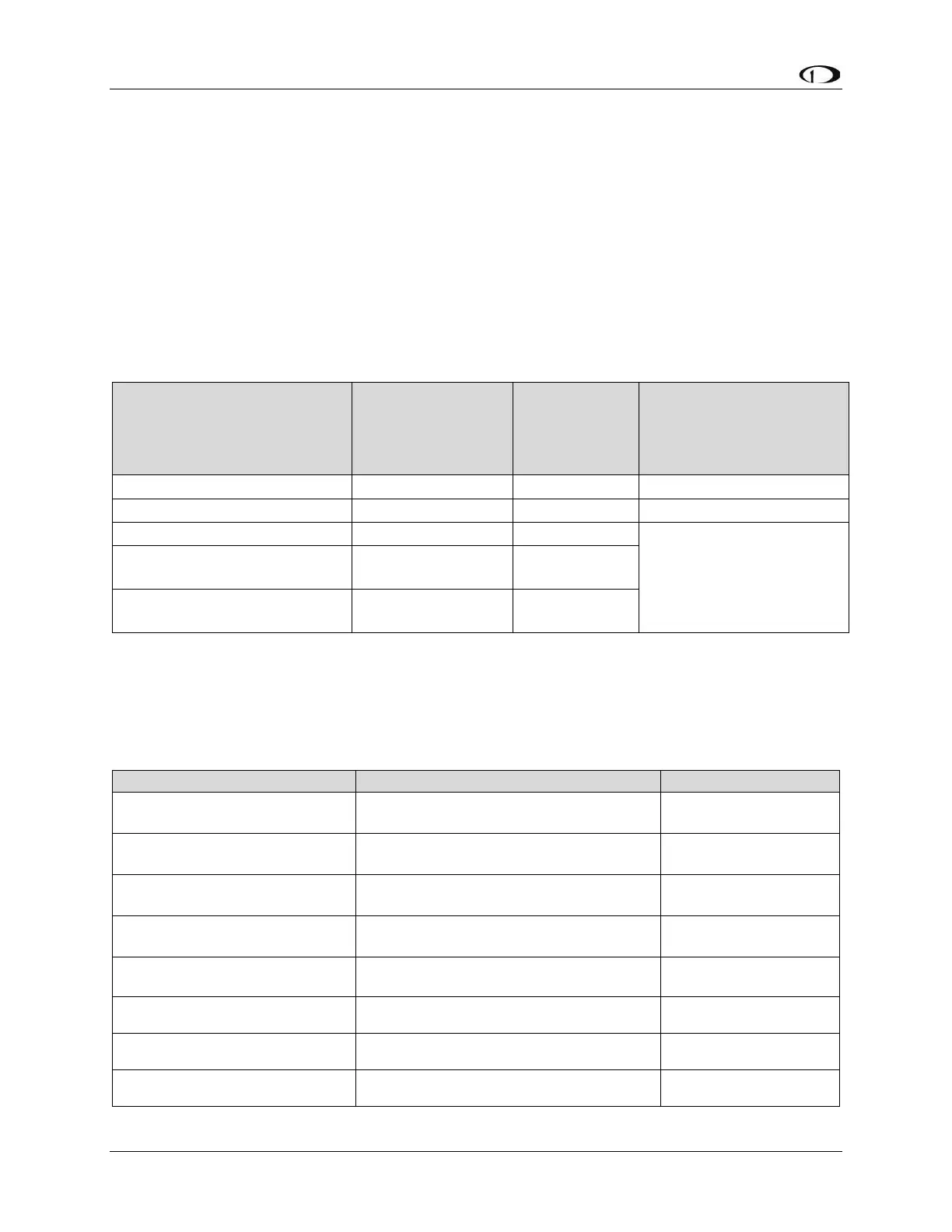
Table 4 contains power specifications for SkyView units that are powered from aircraft
power (not powered by the SkyView Network). The circuit protection recommendations
are suitable for most installations and assume that you are using Dynon Avionics
harnesses and/or are following the wiring advice in this Installation Manual. It may be
possible to use different sized circuit protection if the protective device has suitable load
overhead for the connected device(s). It is also important that circuit protection devices
be appropriately sized to protect the wiring connected to them. 5A circuit protection is
recommend in most cases because that is the smallest circuit breaker that is commonly
available in certified versions, and Dynon Avionics wiring harnesses specify wire of at
least 22 AWG.
Table 4: Power Specifications for SkyView Units Powered by Aircraft Power
Current
requirement
@ 12V DC
Current
Requiremen
t
@ 24V DC
Circuit
Protection
Recommendation
Servos (All) – Not Engaged
SV32 (all variants)
Moving @ 100% torque
SV42 (all variants)
Moving @ 100% torque
*Same current @12V and @24V – does not incorporate a switching power supply.
Table 5 contains physical specifications of major units. Note that dimensions listed in this
table are approximate – see the installation sections of each unit for installation drawings
with precise dimensions.
Table 5: SkyView System Component Physical Specifications
2.47” W x 4.20” H x 3.98” D
(63mm W x 107mm H x 101mm D)
2.47” W x 5.13” H x 3.98” D
(63mm W x 130mm H x 101mm D)
4.71” W x 1.22” H x 2.61” D
(120mm W x 31mm H x 66mm D)
4.10” W x 0.97” H x 2.79” D
(104.2mm W x 24.7mm H x 70.8 D)
3.53” x 1.80” x 1.27” D
(89.7mm x 45.7mm H x 32.4mm D)
4.75” W x 1.09” H x 2.61” D
(121mm W x 28mm H x 66mm D)
3.53” x 1.80” x 1.27” D
(89.7mm x 45.7mm H x 32.4mm D)
SV-COM-T8
(w/mounting tray)
2.5” W x 1.9”H x 6.3” D
(66mm W x 48mm H x 160mm D)