Instrument Panel Design
SkyView HDX System Installation Manual - Revision E 3-5
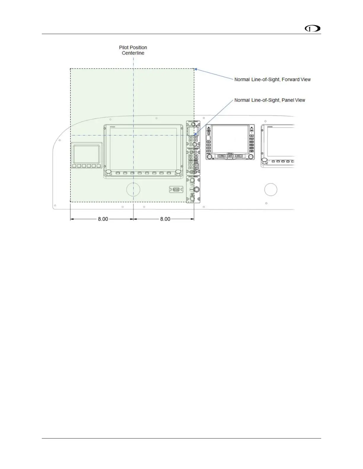
Figure 15: Primary Field-of-View Horizontal Boundary Dimensions
All primary flight information (as defined in Section 0) needs to be located within the
horizontal boundaries of the Primary Field-of-View. The SkyView HDX PFD can be
configured by the pilot to be 100% of the entire display, or it can be reduced to 50% of
the display’s width. When considering where to place the HDX display in the instrument
panel, consider that only the 50% width of the display configured as the PFD must be
located within the primary field-of-view. Doing so may allow more of the EFIS-D10A
Standby Display to fit within the primary field-of-view horizontal boundaries.
According to the AC 23.1311-1C, standby instruments shall be placed “as close as
practicable” to the PFI. This translates into locating the standby display close to the
primary display in a position that will cause the least amount of pilot fatigue during use.
Because a designed pilot’s eye reference point may not have been described by your
airplane manufacturer, and you are retrofitting within the constraints of an existing aircraft,
it is mandatory that you place the Primary Flight Information:
• Horizontally within the boundaries of the Primary Field-of-View.
• Vertically as high in the instrument panel as practical while avoiding any visual
occlusion from potential obstructions such as the glareshield.
As demonstrated in Figure 15, the SkyView HDX display and the EFIS-D10A display can
confortably fit within the calculated boundaries of the Primary Field-of-View as they are
defined by AC 23.1311-1C Section 15.4 Table 3.