Instrument Panel Design
3-6 SkyView HDX System Installation Manual - Revision E
3.3.3 Primary Maximum Field-of-View
According to AC 23.1311-1C, the Primary Maximum Field-of-View is based on the vertical
and horizontal visual fields from the design eye reference point that can be
accommodated with eye movement and minimal head movement.
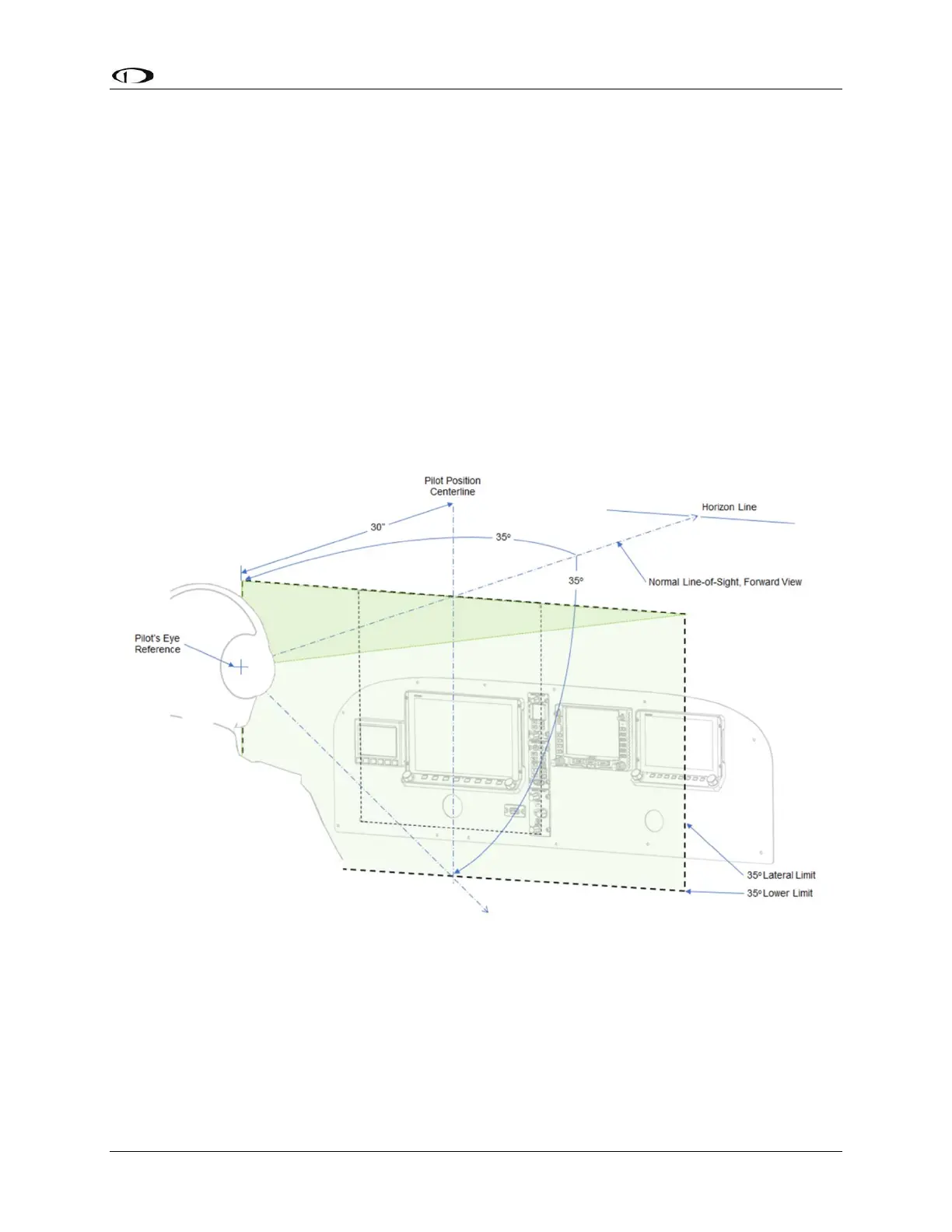
The vertical primary maximum field-of-view limit is defined by the FAA as 30 degrees
below the normal line-of-sight forward view line. The horizontal primary field-of-view is
defined by the FAA as 35 degrees left and right of the horizontal eye reference point (see
Figure 16).
The area of the instrument panel defined by the above parameters represents the area
normally used for important and frequently used information. Ideally, the optional SkyView
HDX control panels will be located within the primary maximum field-of-view, as will any
third-party equipment such as an GPS IFR navigator. An example of primary maximum
field-of-view as it applies to a typical instrument panel located at the AC 23.1311-1C
perscribed position of 30 inches from the pilot’s eye reference position can be seen in
Figure 16.
Figure 16: Primary Maximum Field-of-View
When geometry is applied to an instrument panel located at the 30 inches from the eye
reference point identified in AC 23.1311-1C Section 15.4 Table 3, the resulting horizontal
boundary dimension of the primary maximum field-of-view is 21.0 inches on either side
of the pilot’s position centerline reference, as shown in Figure 17.