164
Shielded cables are recommended when fabricating your own cables.
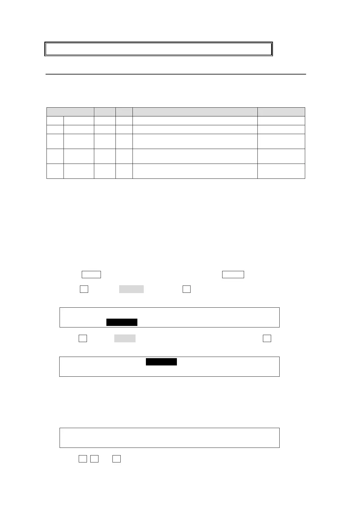
20-1-2. Pin Assignment Examples
The GPI input and output and tally output functions are freely assignable to each pin of the
GPI IN/TALLY OUT connector. This chapter explains how to assign these functions using five
examples describled in the table below.
Performs the BKGD AUTO transitions.
Performs the DSK1 AUTO (MIX) transitions.
Outputs the GPI signal while background
transitions are being performed.
Outputs RED tallies while IN01 is selected
on the PGM bus.
Outputs GREEN tallies while IN01 is
selected on the PST bus.
Two or more functions can be assigned to a GPI input pin. In examples 1 and 2 in the table
above, when Pin 2 is activated by a GPI input pulse, the BKGD and DSK1 AUTO transitions
are simultaneously performed. Up to 60 pairs of pin and function can be set.
See section 20-1-4 "GPI/Tally Function List."
GPI Inputs
Ex. 1: Performs background AUTO transitions using PIN 2.
Ex. 2: Performs DSK1 AUTO (MIX) transitions using PIN 2.
To set the above GPI IN examples, proceed as follows.
Displaying the [SETUP-GPI/TLY] Menu
(1) Press MENU in the SELECT/KEYPAD block, then press SETUP to display the SETUP
top menu.
(2) Turn F1 to select GPI/TLY, then press F1 or the page down button to open the
[SETUP - GPI/TLY] menu.
SETUP :>SYSTEM >INPUT >OUTPUT >PANEL
MENU :>GPI/TLY >FUNCTION>EXT I/F >STATUS
(3) Turn F1 to select GPI I/O in the [SETUP - GPI/TLY] menu, then press F1 or the page
down button to open the [SETUP - GPI/TLY - GPI I/O] menu.
SETUP :>TLY COL >GPI I/O >TALLY1 >TALLY2
Setting GPI IN Functions
(1) PAGE 1 in the [SETUP - GPI/TLY - GPI I/O] menu determines IN or OUT for each pin.
All pins are set to IN as factory default settings. Therefore, no settings from this page
are required. Go to the next page.
GPI/TLY :GPIIN:<- I/O ASSIGN(F2) ->:1/3
GPI I/O : =OFF:IIIIIIII IIIIIIII IIIIIIII:
(2) Turn F1, F2 and F3 to set as shown below to assign the function for Example 1.