17
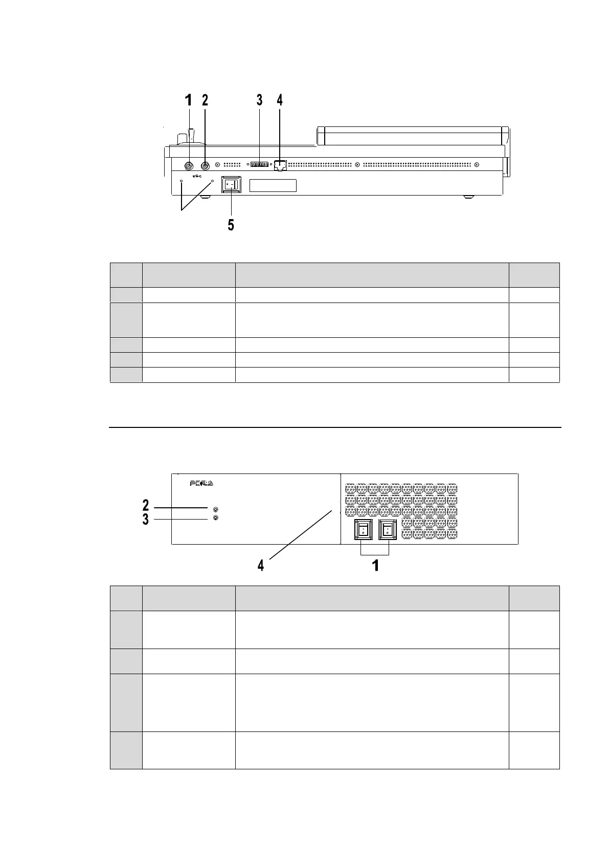
Rear Panel
Supply power (12 V DC) using the supplied AC adaptor.
Optional power supply (HVS-XT110PSM) for power
redundancy. Supply power (12 V DC) using the supplied
AC adaptor.
For maintenance use. Do not change.
Switch used to turn unit power ON / OFF.
2-2. HVS-XT100
Front Panel
Power switch1
Power switch2
Switch used to turn unit power ON / OFF.
Set both switches to ON if redundant power supply is
configured.
Power indication is lit green when power switch is set to
ON and power is applied to unit.
Indicates fan alarm status.
Normally unlit, the indicator blinks red when an alarm
occurs. In such case, power off the system and consult
your FOR-A supplier. (It also blinks red when a power
supply does not work in redundant configuration.)
Used to connect a USB flash drive for image file import /
export or system setting backup.
(USB1.1, Type-A)
PO WER 2
O FF
ON
DIG ITAL VIDE O SW ITCHER
POWER
ALARM
PO WER 1
USB
HVS-XT100
DC12V
1 2
POW ER
OFF ON
MODE SW TO MU
Holes for securing
cables with clamps