183
20-3-5. Crosspoint Switches with Control Buttons (Execution)
Assume that router functions are assigned to the router control buttons as shown
in the table below.
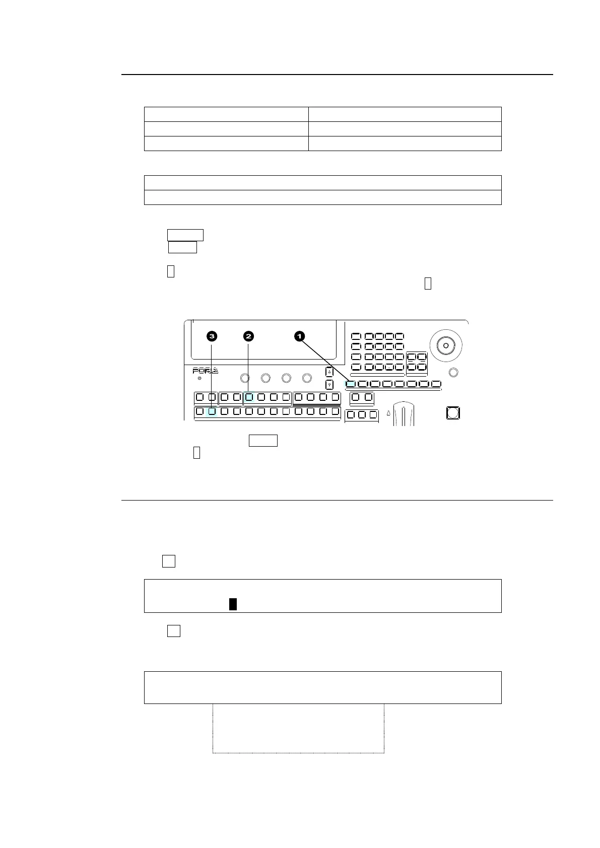
USER 1 on the control panel
Destination channels 1 to 4
KEY/AUX bus buttons 1 to 8
To execute the following commands:
Connect Source channel 2 to Destination channel 1.
Connect Source channel 4 to Destination channel 2.
Proceed as follows:
(1) Press USER1 to enable the router control buttons.
(2) Press AUX1 to select Destination 1. The source channel button currently connected to
Destination 1 will light orange.
(3) Press 2 on the KEY/AUX bus to change the source channel to 2. The HVS-XT110 sends
the crosspoint switch command to the router. The bus button 2 on the KEY/AUX will turn
orange after having received a successful response from the router.
(4) In the same way, press AUX2,
(5) Then press 4 on the KEY/AUX bus.
20-3-6. Displaying Destination / Source Settings
The switcher can obtain and display the current destination / source settings (crosspoints) on
the router as in the procedure below.
(1) Go to PAGE4 in the [SETUP - EXT I/F - ROUTER] menu.
(2) Turn F1 to select a level.
EXT I/F : LEVEL : XPT :PRESET : : 4/6
(3) Press F2. The current crosspoint pairs (Destination - Source) on the router are listed as
shown below: Up to 6 pairs can be displayed per menu page. Use the page up or down
button to move among pages.
ROUTER : 1-1 2-2 3-3 : : 1/XX
XPT : 4-4 5-5 6-6 : >BACK :
USB MEMORY
DIGIT AL V IDEO SWIT CHER HVS-
XT
SIZE
(PUS H to DEF)
1 2 3 4 5 6 7 8
USER BUTTON
RE V NOR/REV
DIR ECTION
BLACK
TRANS
BKGD KEY1 KEY2
ALA RM
F1 F2 F3 F4
PAGE
1 1 1
1
2 2 2 3 4
2 3 4 5 6 7 8 9 10 11 12
KEYER DSK AUX
KEY/AUX
PGM PR EV CLE AN MV
MENU ATTACH
DIRECT
PATT
DETACH
SETUP
KEY1
POSITION
POS ROT
2D DVE
WIPE
POS
MENU
JOYSTICK
8 9
4 5 6
STILL MATT F ILE
KEY2 DSK1 DSK2
EVENT
MACRO
1 2 3
0
CLEAR
RECALL S TORE
ENTER
CK E FFECT
TRANS RATE WIPE
SELECT/K EYPAD
±
7