38
5-2. How to Assign Sources to Bus Buttons
Primary and optional video inputs, internally generated signals (black, mattes, etc.), and
captured stills can be freely assigned to bus buttons using the procedure below.
Signal-to-Button mappings are shared on the PGM/PST and KEY/AUX bus.
(1) Press MENU, then SETUP to display the SETUP menu top page.
(2) Turn F1 to select INPUT. Press F1 or the page down button to display the menu.
(3) Turn F1 to select ASSIGN. Press F1 or the page down button to display the [SETUP - INPUT
- ASSIGN] (1/3) menu.
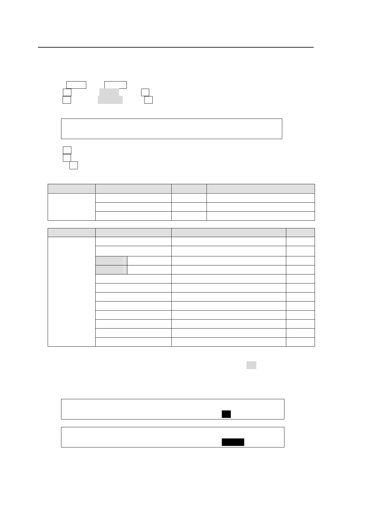
INPUT :BUTTON : SIGNAL NAME :INHIBIT: 1/3
OU ASGN : =01 : =IN04 =IN04 : =OFF :
(4) Turn F1 to select a bus button under BUTTON.
(5) Turn F2 to select the signal to be assigned under SIGNAL. Users can also select a signal by
turning F3 under NAME. SIGNAL and NAME are linked to each other.
See section 5-1. "How to Assign User Names to Sources" for more details.
1-20, sft1-sft20 (shifted buttons)
01 to 12,
sft01 to sft12
(shifted
buttons)
Video input to rear connectors 1-8
Video input to rear connectors 1-12
Still key (alpha channel) images 1 and 2
Internally generated color bar signal
To Disable Bus Button Operation
Users can inhibit operation of specific bus buttons. First, set INHIBIT to ON for a bus button on
PAGE 1, and the selected bus button on the PGM/PST is set to INHIBIT. Next, set INHIBIT to
ENABLE on PAGE 3 to enable the bus button inhibit function. Bus buttons, set to INHIBIT
cannot select signals. The INHIBIT setting has no effect on the KEY/AUX bus.
INPUT :BUTTON : SIGNAL NAME :INHIBIT: 1/3
OU ASGN : =01 : =IN04 : =IN04 : =ON :
INPUT :SELECT : SHIFT : LINK :INHIBIT: 3/3
ASSIGN : =OU : =NORML: =--- : =ENABL: