21
2-4. Interfaces
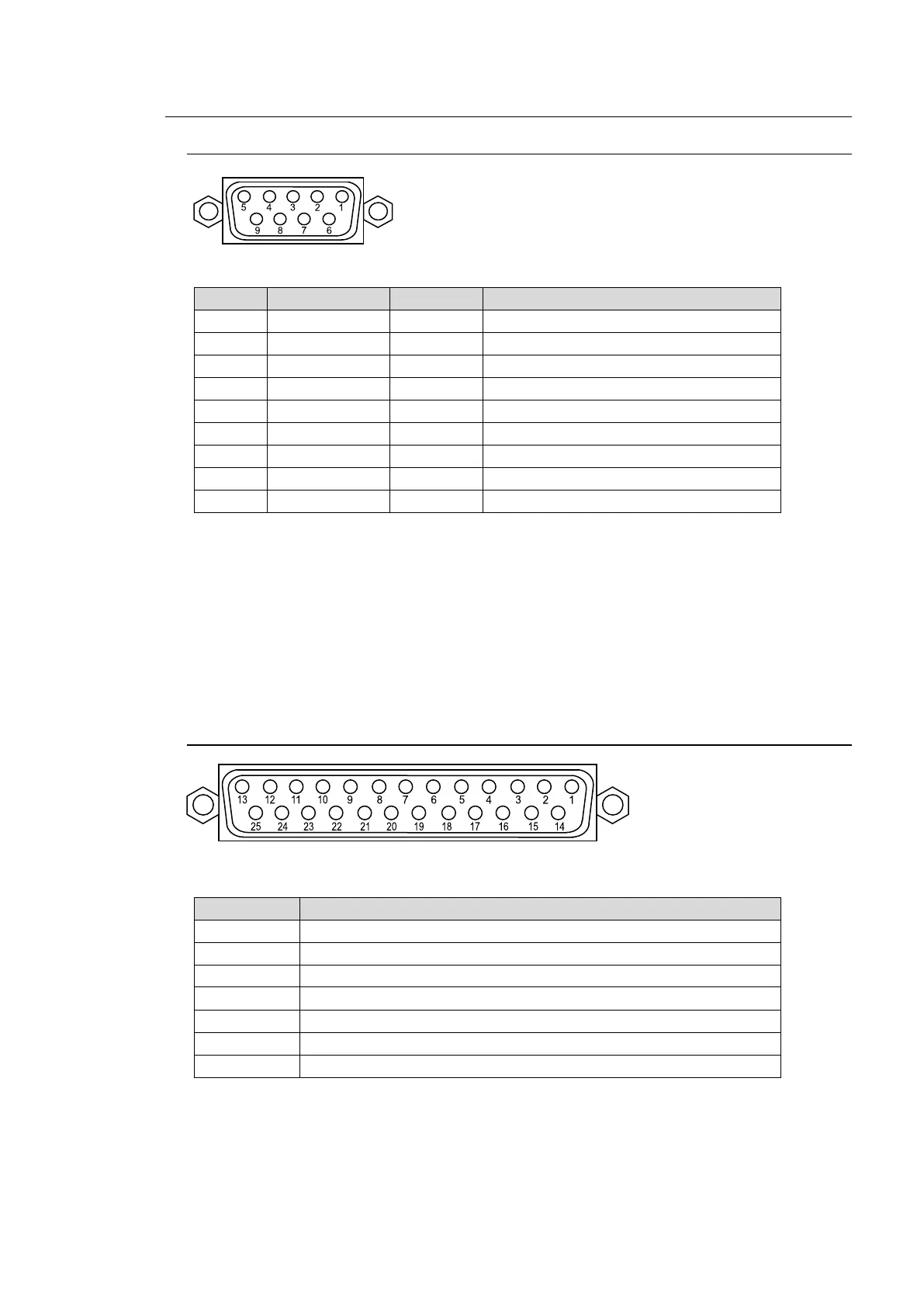
2-4-1. RS-422 Connector 1-2
Pin Assignment Table (9-pin D-sub ,female, with inch screws)
RS-422 ports are used for the following device connections. See the related chapters to
configure the connections.
HVS-30RU: See section 20-6. "Remote Panel (HVS-30RU)."
Tally Units: See section 20-1-3. "Sending Tally Signals to Tally Units."
VTR/VDCP devices: See section 20-2. "VTR / VDCP Control."
Routers: See section 20-3. "Router Control."
Editor: See section 20-4 "Editor Control."
2-4-2. GPI IN/TALLY OUT Connector
Pin Assignment Table (25-pin D-sub, female, with inch screws)
BKGD AUTO TRANS (input) (default setting)
KEY1 AUTO TRANS (input) (default setting)
KEY2 AUTO TRANS (input) (default setting)
DSK1 AUTO TRANS (input) (default setting)
DSK2 AUTO TRANS (input) (default setting)
Unassigned (default setting)
See section 20-1-1. "GPI IN/TALLY OUT Connector" for more details.