55
7. Bus Operation
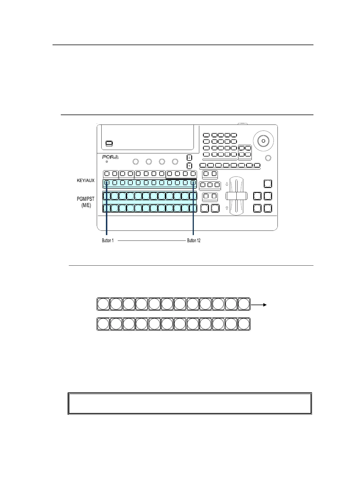
Video signals that are input to the switcher are assigned to the bus buttons on the control panel for
usage. The assigned signals are shared by the M/E(PGM/PST) and KEY/AUX bus sections.
As factory default settings, video inputs, Stills and Mattes are assigned to the bus buttons. The
video source assignments are freely changeable. To prevent accidental button operation, the
Button Inhibit function is also available.
See section 5-2. "How to Assign Sources to Bus Buttons."
7-1. Selecting Video Sources
7-1-1. Selecting Video Sources on the PGM/PST
Press the desired bus button on the PGM bus. The button light will turn red and the video
signal assigned to the selected bus button is displayed on the program output screen.
Press the desired bus button on the PST bus. The button light will turn orange and the video
signal assigned to the selected bus button is displayed on the preview output screen. Then
move the fader lever from end to end to check how the button indication changes as the
signals are switched. Once the transition is complete, the selected signals on PGM and PST
are switched (flip-flop).
The switcher's primary operation is to select the next video on the PST bus and send it to air
via transition. And to repeat the process over and over.
Users can change the M/E bus mode from PGM/PST to A/B.
See section 7-2. "Button Switching Mode in M/E Bus."
USB MEMORY
DIGITAL VIDEO SWITC HER HVS-
XT
SIZE
(PU SH to DEF)
1 2 3 4 5 6 7 8
USER BUTTON
REV NOR /REV
DIRECTION
BLACK
TRANS
BKGD KEY1 KE Y2
NEXT TRANSITION
MIX WIPE
KEY1 KEY2
TRANSITION TYPE
AUTO CUT DSK1 DSK2
ALARM
F1 F2 F3 F4
PAGE
1 1 1
1
2 2 2 3 4
2 3 4 5 6 7 8 9 10 11 12
KEYER DSK AUX
KEY/AUX
PGM PR EV CLEAN MV
PGM
PST
1 2 3 4 5 6 7 8 9 10 11 12
MENU ATTACH
DIRECT
PATT
DETACH
SETUP
KEY1
POSIT ION
POS ROT
2D DVE
WIPE
POS
MENU
JOYSTICK
8 9
4 5 6
STILL MAT T FILE
KEY2 DSK1 DSK2
EVENT
MACRO
1 2 3
0
CLEAR
RECALL S TORE
ENTER
CK EFF ECT
TRANS RATE WIPE
SELECT/KEYPAD
±
7
PGM
PST
1 2 3 4 5 6 7 8 9 10 11 12