172
20-2. VTR / VDCP Control
The switcher can control video tape or video disk recorders via RS-422 using the VTR or VDCP
protocol. Up to 2 channels (two devices) are available. Connect a device to a desired RS-422
port, configure the port and select a channel for VTR or VDCP following the procedures in this
chapter.
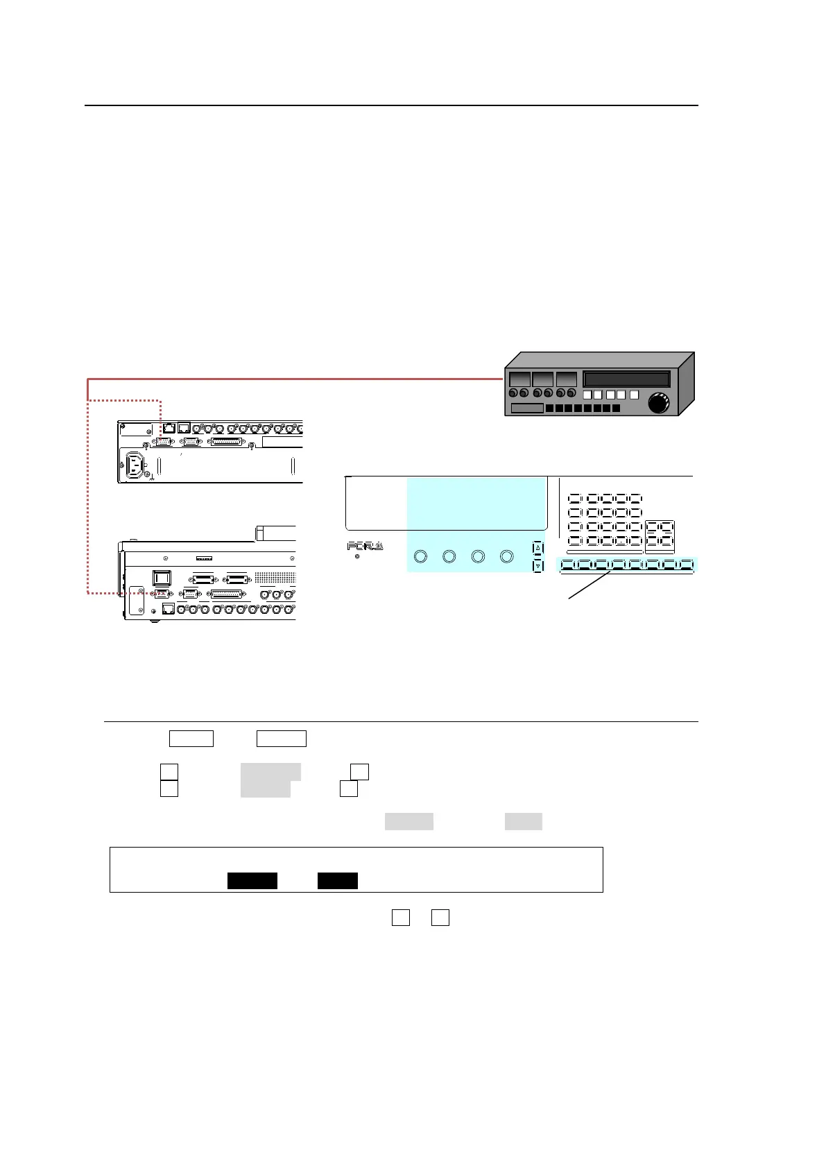
System Configuration Example
1) Connect an HVS-XT110 to a VTR using an RS-422 port and configure the port.
See section 20-2-1.
2) Assign a VTR channel to the RS-422 port.
See section 20-2-2.
3) Control the VTR using the VTR/VDCP menu (see section 20-2-3) or by using USER buttons
(see section 14. "USER Buttons.")
20-2-1. RS-422 Port Settings (VTR/VDCP)
(1) Press MENU, then SETUP in the SELECT/KEYPAD block to display the [SETUP] top
menu.
(2) Turn F1 to select SYSTEM. Press F1 to go to the [SETUP - SYSTEM] menu.
(3) Turn F1 to select RS-422. Press F1 to go to the [SETUP - SYSTEM - RS-422] menu.
(4)When connecting a VTR to RS-422 (1) port, set the menu as shown below.
If your device supports VDCP protocol, set VDCP1 instead of VTR1 under FUNC.
SYSTEM :SELECT :FUNC :BAUD :PARITY : 1/1
RS-422 : =PORT1 : =VTR1 : =38400: =ODD :
(5) Change BAUDRATE and PARITY using F3 or F4, if needed.
(6) Reboot the switcher.
See section 19-1. "Rebooting System."
REF OUT 1 12 3 4 5 6 7 8 2 3 4REF IN
HDMI OUT
A UX
5 6 7 8
A UX
LAN
SDI INPUT
9 10 11 12
SDI I NPUT
GPI IN/TA LLY OUT
DC12 V IN
1 2
MODE SW
POW ER
OFF ON
GENLOCK
RS-422
1 2
REF OUT 1
1
2 3 4 5 6 7 8
2 3 4
A
B
C
REF IN
1 2
2
AC100-240V 50/60Hz INAC100-240V 50/60Hz IN
1
TO OU
LAN GENLOCK SDI I NPUT
RS-422 GPI IN/TALLY OUT
HDMI OUTAUX
USB MEMORY
DIGIT AL VIDEO SWITCHER
1 2 3 4 5 6 7 8
USER BUTTON
ALARM
F1 F2 F3 F4
PAGE
MENU ATTACH
DIRECT
PATT
DETACH
SETUP
KEY1
POS ROT
2D DVE
WIPE
POS
MENU
JOYST ICK
8 9
4 5 6
STILL MATT FILE
KEY2 DSK1 D SK2
EVENT
MACRO
1 2 3
0
CLEAR
RECALL S TORE
ENTER
CK EFFECT
TRAN S RATE WIPE
SELECT/KEYPAD
±
7
Controlling VTR using
the VTR/VDCP menu.
Controlling VTR using user buttons.