167
20-1-3. Sending Tally Signals to Tally Units
Up to three tally units can be connected to the switcher by cascading them through an
RS-422 port.
Two types of Tally Units, Open Collector and Relay types, can be used.
See the "HVS-TALOC/TALR20/32 Operation Manual" for details on tally unit setup.
Communication Settings for Tally Units
Set the Communication parameters before setting up tally signals. Tally Units are connected
to RS-422 (2) in this example.
(1) Open the [SETUP - SYSTEM - RS-422] menu.
(2) Turn F1 to select PORT2.
(3) Turn F2 to select TALLY. Set the parity to EVEN. The baud rate is automatically set
according to the tally unit.
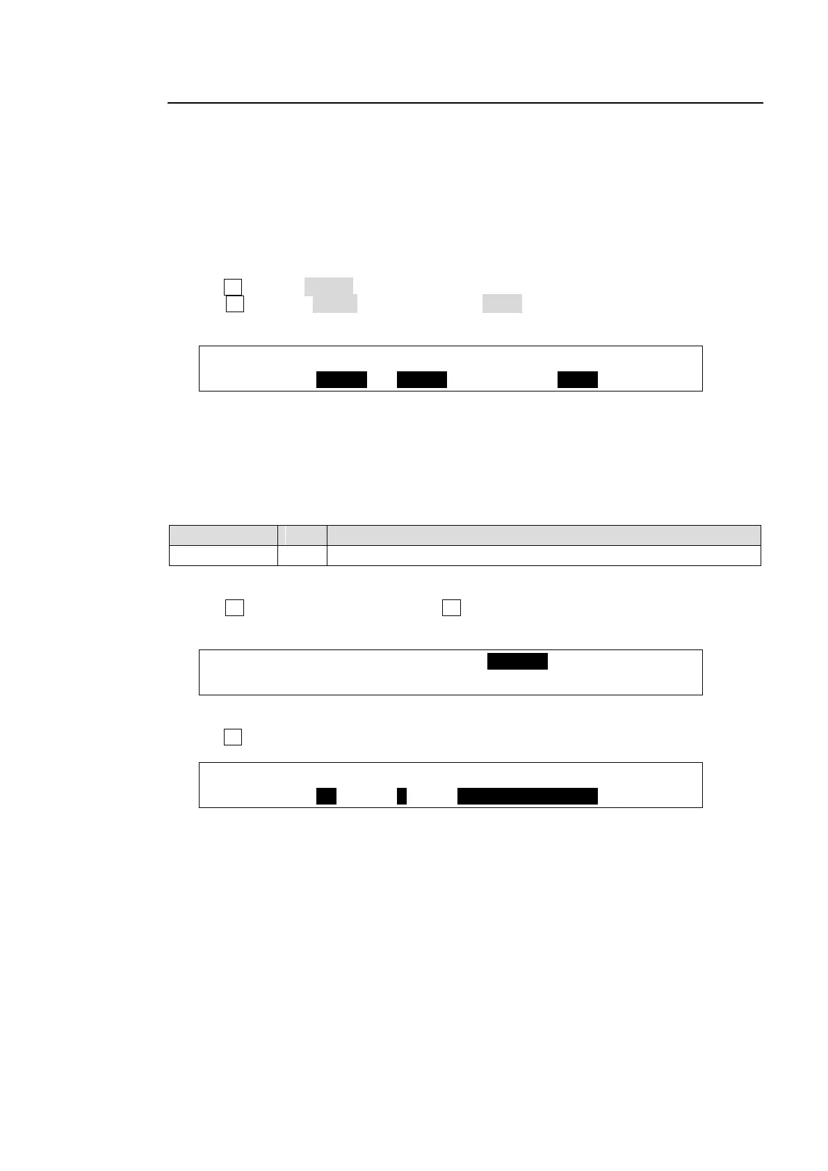
SYSTEM :SELECT : FUNC : BAUD :PARITY : 1/1
RS-422 : =PORT2: =TALLY: =38400: =EVEN :
(4) Restart the switcher.
See section 19-1. "Rebooting System."
Tally Unit Settings
The following example sets the following tally signal for TALLY 1.
The switcher and Tally units share the same tally color settings. (See the previous page.)
Outputs RED tallies while IN01 is selected on the PGM bus.
(1) Open the [SETUP - GPI/TLY] menu.
(2) Turn F1 to select TALLY1 and press F1 to display the [SETUP - GPI/TLY - TALLY1]
menu.
SETUP :>TLY COL >GPI I/O >TALLY1 >TALLY2
(3) Select the pin number and set the function as shown below.
Turn F1 to set ENABLE to ON to activate all tallies in TALLY1.
GPI/TLY :ENABLE :P NO : FUNCTION : 1/1
TALLY1 : =ON : =1 : =RED TALLY-IN01