Seven dedicated outputs are available for control, warning, and error functions. These
open-collector outputs are slew-limited. Optional 10K ohm pull-up resistors, tied to a
common point for use at either +5 or +24 VDC, are available via jumper JMP 1.
Note: To avoid damage if external pull-up resistors are used (that is, without jumper JMP1
installed), ensure that the external voltage does not exceed +30VDC.
Failure to properly configure the GPIO Port can result in damage to the printer
and / or connected devices.
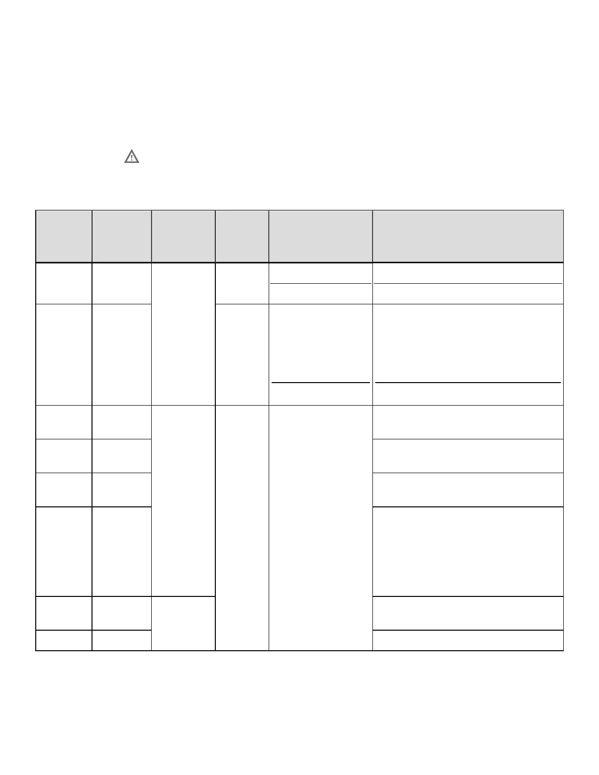
The following table details the GPI/O A pin assignments, settings, and functions:
Pin
Number
Signal
Name
Signal
Direction
[1]
Jumper Position Function / Description
1 Ground
N/A
JMP 8
Installed
Removed
Printer chassis is used.
Ground must be supplied.
2 +5 VDC JMP 9
Installed
Removed
Printer +5VDC is used (.5 amp
maximum).
Note: Drawing more than .5 amps
can cause unreliable printer
operation.
+5VDC must be supplied.
3
Start Of
Print
[2]
Input
N/A N/A
Programmable
4
Slew
Label
Programmable
5
Toggle /
Pause
The printer pauses when the signal
is taken LOW.
6 Reprint
The last label is reprinted exactly,
with no increment or time stamp
changes; recommended for use
during error conditions. Keeping
this signal LOW results in non-stop
printing.
7 +24 VDC
N/A
Printer +24 VDC (1.5 amp
maximum)
8 Ground Printer chassis.
DPL Command Reference
259
 Loading...