3-102 Return to Section Topics 4200-900-01 Rev. K / February 2017
Section 3: Common Device Characterization Tests Model 4200-SCS User’s Manual
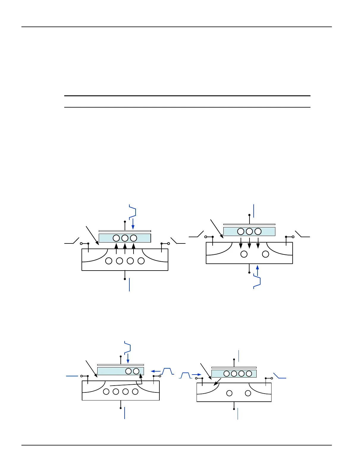
Figure 3-82 shows examples of tunneling to move charge to and from the FG.
• The electric field and the preferred direction of electron flow are indicated by the
black arrows.
• The signal applied to each device terminal are indicated by the blue text and blue
features.
NOTE Both the drain and source are not connected to any test instrumentation.
This condition may also be called floating or high impedance. Figure 3-83 shows
examples of moving charge using HEI. These conditions are only examples with
approximate voltage values, and both pulse width and pulse height will vary
depending on device structure and process details.
There are many other ways to provide similar electric fields and balance
performance across a variety of parameters: program or erase speed, retention
longevity, adjacent cell disturbance, endurance, and others.
Figure 3-82
Fowler-Nordheim tunneling program and erase.
Figure 3-83
Hot Electron Injection (HEI) program and erase.
- - - -
CG
FG
S D
- - -
~18-20V
B
0V
Open Open
Tunnel Oxide
- -
CG
FG
S D
- - -
B
Open Open
Tunnel Oxide
0V
~19-21V
Program using FN tunneling Erase using FN tunneling
- - - -
CG
FG
S D
-
~10-14V
B
0V
0V or GND
Tunnel Oxide
~5-7V
-
- -
CG
FG
S D
-
B
0V
Open
Tunnel Oxide
-
~10-14V
0V
- -
Program using hot electron injection Erase using HEI

 Loading...