3-116 Return to Section Topics 4200-900-01 Rev. K / February 2017
Section 3: Common Device Characterization Tests Model 4200-SCS User’s Manual
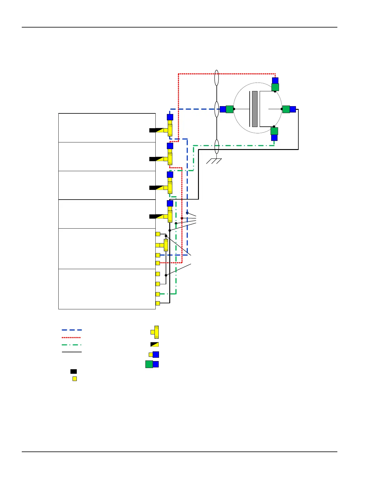
Figure 3-95
Flash connections – program/erase and endurance testing using direct connection to a
single, stand-alone 4-terminal device
Figure 3-96 shows the connections for test similar to Figure 3-91 that are used for
disturb testing. It is strongly recommended to use a switch matrix for testing array
test structures, whether for endurance or disturb. However, it is possible to
perform a limited test of an array structure without using a switch matrix, as one
example is shown in Figure 3-96.
4205-PG2 #1
Trigger IN
Chan 2
4205-PG2 #2
4.25" (11 cm)
8" (20 cm)
Chan 1
Chan 2
Trigger IN
Trigger OUT
Chan 1
Trigger OUT
4200-SMU/
4210-SMU
Force
4200-SMU/
4210-SMU
Force
4200-SMU/
4210-SMU
Force
5' (1.5 m)
BNC
4200-SMU/
4210-SMU
Force
5' (1.5 m)
BNC
5' (1.5 m)
5' (1.5 m) BNC
DUT
G
D
S
B
DUT Connections
Bulk
Gate
Drain
Source
Note: All interconnect on
instrument chassis are white
SMA cables. Cables from the
instrument to device are BNC
coax. Use Triax to BNC
adapters if necessary to
connect to probe manipulators .
LEMO Triax Connector
Instrument Connectors
SMA Connector
SMA Tee, male-female-male
Adapters
LEMO Triax -to-SMA Adapter
SMA male to BNC female
Triax female to BNC female

 Loading...