4200-900-01 Rev. K / February 2017 Return to Section Topics 3-117
Model 4200-SCS User’s Manual Section 3: Common Device Characterization Tests
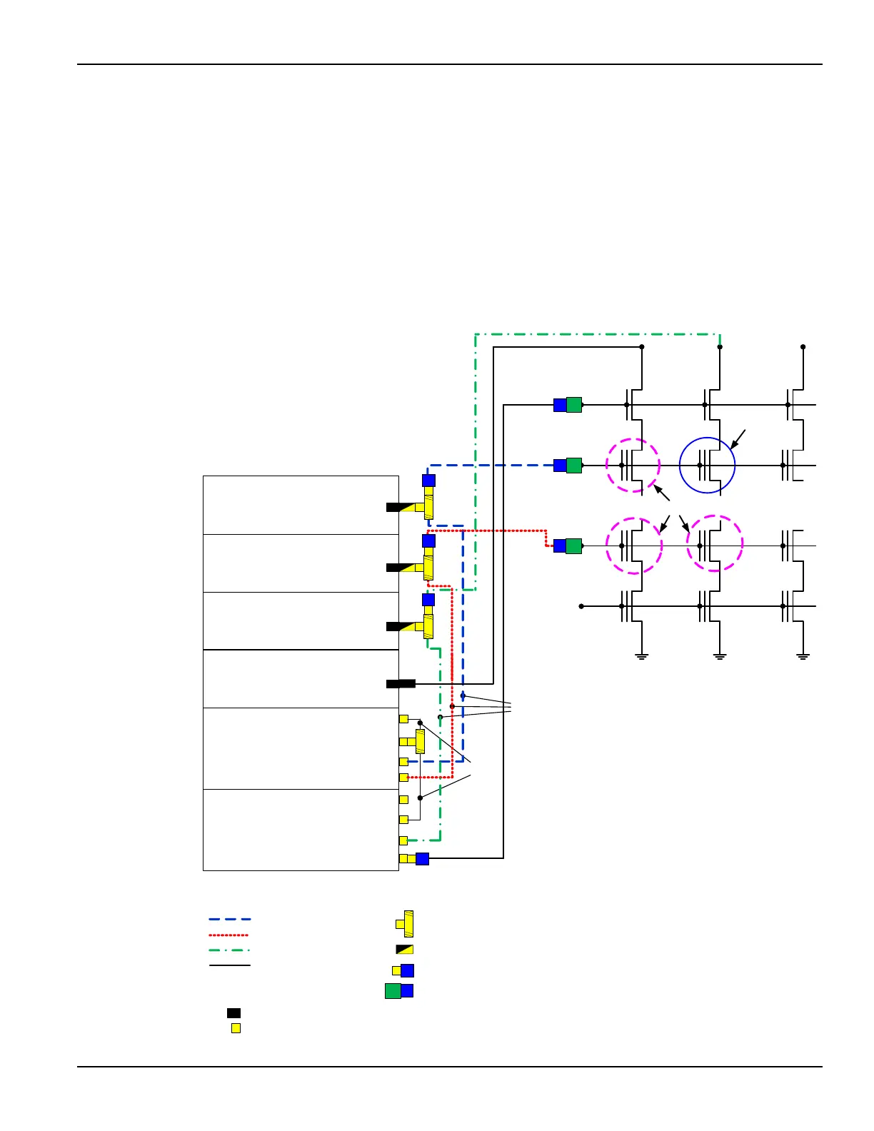
Figure 3-96 shows connections to an array test structure, where one of the four
SMU+PG2 channels was split to provide a total of five test signals to provide the
minimum necessary channels for the select pins (Bit Line Select, Bit Lines 1 and
2), to the pulse DUT (circled in blue), and the measure DUTs (circled in dashed
purple). Figure 3-96 allows for pulsing one DUT while performing disturb
measurements on the three DUTs labeled Measure. The preferred connection
method for disturb testing, or any testing of a an array DUT, is to add a switch
matrix, as shown in Figure 3-97.
Figure 3-96
Flash direct DUT connections – Disturb testing
4205-PG2 #1
Trigger IN
Chan 2
4205-PG2 #2
4.25" (11 cm)
8" (20 cm)
Chan 1
Chan 2
Trigger IN
Trigger OUT
Chan 1
Trigger OUT
4200-SMU/
4210-SMU
Force
4200-SMU/
4210-SMU
Force
4200-SMU/
4210-SMU
Force
4200-SMU/
4210-SMU
Force
WL1
Bit Line Select
WL2
WLn
Pulse this
cell
V
PGM
Measure
...
...
Bit Lines
Word Lines
SMU & PG2
SMU & PG2
SMU & PG2
SMU only
PG2 only
BL1 BL2
78" (2 m) Triax
5' (1.5 m)
BNC
5' (1.5 m) BNC
78" (2 m)
Triax
5' (1.5 m) BNC
5' (1.5 m)
5' (1.5 m)
BNC
Note: All interconnect on instrument
chassis are white SMA cables.
Cables from the instrument to
device are BNC coax, except for the
direct SMU4 connection, which is
black Triax. Use Triax to BNC
adapters if necessary to connect to
probe manipulators .
LEMO Triax Connector
Instrument Connectors
SMA Connector
SMA Tee, male-female-male
Adapters
LEMO Triax -to-SMA Adapter
SMA male to BNC female
Triax female to BNC female
DUT Connections
PG: BL Select /
SMU: BL1
WL1 / Gate
WL2 / Gate
BL2 / Drain

 Loading...