215184 95 Revision A
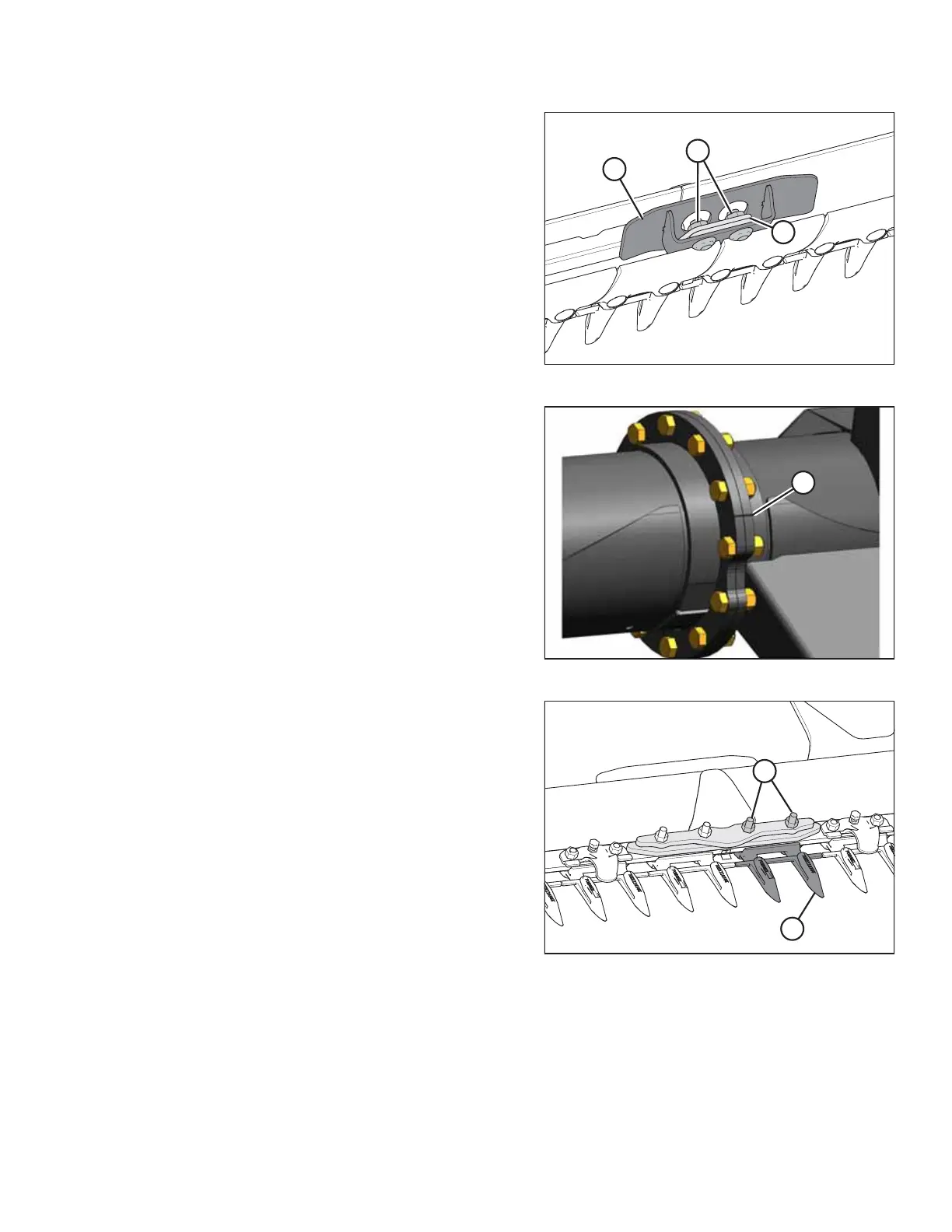
Figure 3.188: Connector and Cutterbar Lugs
6. Retrieve all parts from the hardware bag labelled A.
7. Position connector (A) onto cutterbar lugs (B) as shown,
and install with 5/8 x 1-1/4 in. carriage bolts and lock
nuts (C) removed in 3.3.3 Removing Extension, page 94.Do
NOT fully tighten.
Figure 3.189: Aligned Flanges
8. Use alignment marks (A) on flanges for proper alignment of
end frame prior to fully tightening bolts. Torque flange
bolts to 271 Nm (200 lbf·ft).
NOTE:
If Grade 5 bolts are used, torque them to 203 Nm
(150 lbf·ft). Refer to 12.2 Torque Specifications, page 506
for bolt identification.
Figure 3.190: Guard
9. Install guard (A) and cutterbar wearplate at split with two
7/16 x 2-1/2 in. special carriage bolts and lock nuts (B)
removed in 3.3.3 Removing Extension, page 94. Torque
bolts to 81–95 Nm (60–70 lbf·ft).
ASSEMBLING THE HEADER AND FLOAT MODULE