215184 98 Revision A
Figure 3.194: View from behind Cutterbar
7. Position two castings (A) inside cutterbar from backside and
slide onto support angle at the outboard location as shown.
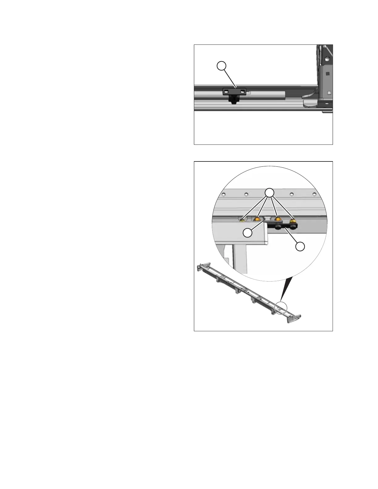
Figure 3.195: View from above Deck
8. Remove four nuts (A) from the inboard deck front support
casting (B) and remove bar (C). Do NOT remove casting (B).
Retain parts for reinstallation.
9. Position deck extension in header. Use wooden blocks to
support deck.
ASSEMBLING THE HEADER AND FLOAT MODULE