215184 184 Revision A
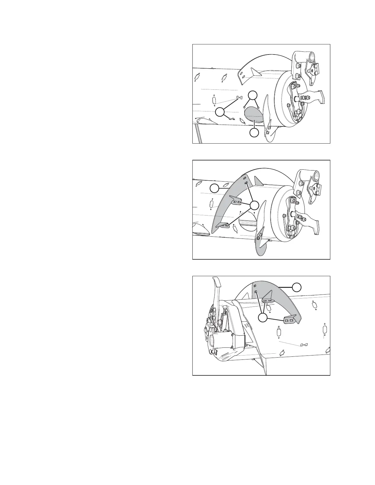
Figure 6.19: Wide Configuration – Right Side
2. Remove bolts (A) and remove access cover (B) from the
right side of the auger. Retain for reassembly.
NOTE:
If necessary, remove multiple access covers.
3. Remove and discard two flighting slot plugs (C) from the
right side of the auger.
Figure 6.20: Medium Configuration – Right Side
4. Install bolt-on flighting (A) on the right side of the auger as
shown, and secure with six carriage head bolts and six nuts
at locations (B).
IMPORTANT:
Bolt heads must be installed on the inside of the auger to
prevent damaging internal components.
NOTE:
Flighting performs best when no gaps are present. If
desired, use silicone sealant to fill the gaps.
5. Torque all nuts and bolts to 47 Nm (35 lbf·ft) to eliminate
deflection on flighting, then torque them to 58–64 Nm
(43–47 lbf·ft).
Figure 6.21: Medium Configuration – Left Side
6. Repeat Step 2, page 184 and Step 3, page 184 at the left
side of auger.
7. Install bolt-on flighting (A) on the left side of the auger as
shown, and secure with six carriage head bolts and six nuts
at locations (B).
IMPORTANT:
Bolt heads must be installed on the inside of the auger to
prevent damaging internal components.
NOTE:
Flighting performs best when no gaps are present. If
desired, use silicone sealant to fill the gaps.
8. Torque all nuts and bolts (B) to 47 Nm (35 lbf·ft) to
eliminate deflection on flighting, then torque them to
58–64 Nm (43–47 lbf·ft).
9. Remove extra auger fingers. A total of 22 fingers are recommended for this configuration. For instructions, refer to
6.2.11 Removing Feed Auger Fingers, page 200.
FLOAT MODULE SETUP AT DEALER