215184 191 Revision A
Figure 6.36: Narrow Configuration – Right Side
5. Remove flighting slot plug (A), bolt, and tee nut if
converting your auger to the Wide configuration. Retain for
reinstallation, and continue to Step 6, page 191. Otherwise,
leave plug (A), bolt, and tee nut in place on the auger and
continue to Step 10, page 191 to complete the Ultra Wide
conversion.
NOTE:
Only two flighting slot plugs (A) should be removed—one
from each outboard side of the auger.
Figure 6.37: Wide Configuration – Right Side
6. Install new bolt-on flighting (A) using six carriage head bolts
and nuts (B) on the right side of the auger.
IMPORTANT:
Bolt heads must be installed on the inside of the auger to
prevent damaging internal components.
7. Reinstall flighting slot plug (C) previously removed in Step 5,
page 191.
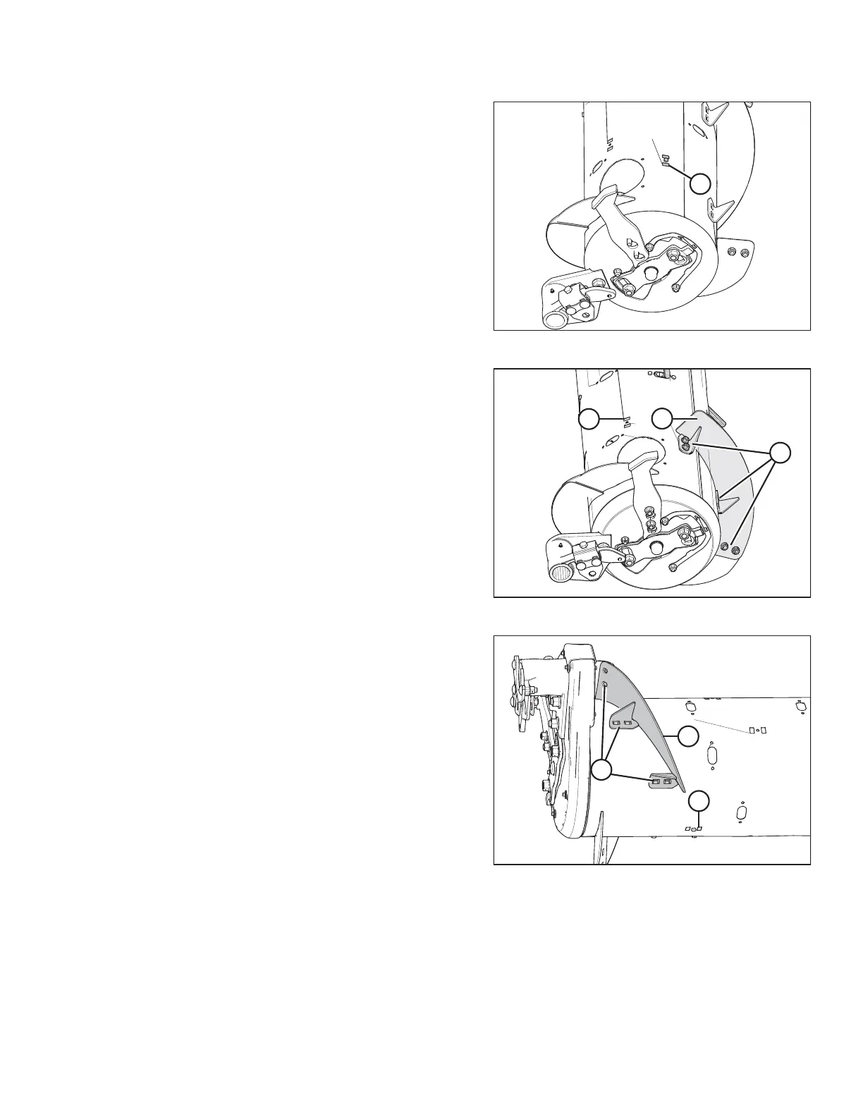
Figure 6.38: Wide Configuration – Left Side
8. Install new bolt-on flighting (A) on the left side of the auger
using six carriage head bolts and nuts (B).
IMPORTANT:
Bolt heads must be installed on the inside of the auger to
prevent damaging internal components.
9. Reinstall flighting slot plug (C) previously removed in Step 5,
page 191.
10. Install the remaining flighting slot plugs (MD #213084)
using the M6 hex head bolts (MD #252703) and tee nuts
(MD #197263) in locations previously used to mount
removed flighting in Step 3, page 190 and Step 4, page 190.
11. Install additional auger fingers. There should be a total of
30 fingers in this configuration. Auger fingers and all
required parts are included in kit. For instructions, refer to
6.2.10 Installing Feed Auger Fingers, page 198.
FLOAT MODULE SETUP AT DEALER