215184 210 Revision A
Figure 7.12: Multicoupler on Float Module
4. At the multicoupler, connect the cab draper extension
harness (MD #304211) to the float module as follows:
• Connector C3A – If the In-Cab Side Draper Speed
Control kit has been installed, plug connector C3B on
the valve drive harness into connector C3A. If the In-
Cab Side Draper Speed Control kit has not been
installed, leave C3A unconnected.
• Connector C5B – Plug connector C5B (A) into
connector C5A on the completion harness.
NOTE:
Connectors C3A and C5B are shipped with caps. The caps
need to be removed in order to connect these connectors.
Figure 7.13: Switch Harness Routing
5. Route cab draper extension harness (A) along the side of
the combine feeder house to the underside of the
combine cab.
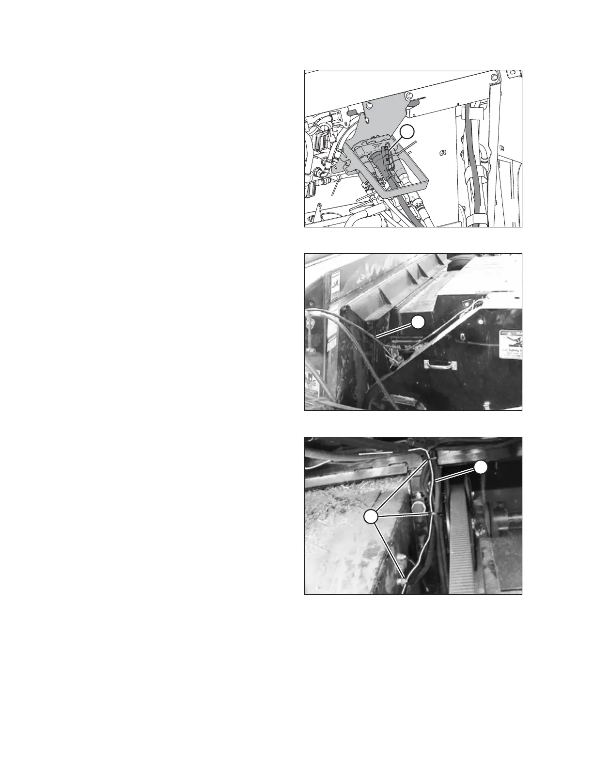
Figure 7.14: Left Side of Feeder House
6. Use cable ties (MD #16661) to fasten cab draper extension
harness (A) to the main harness on the left side of the
feeder house and under the cab floor at locations (B).
ATTACHING HEADER TO COMBINE