215184 223 Revision A
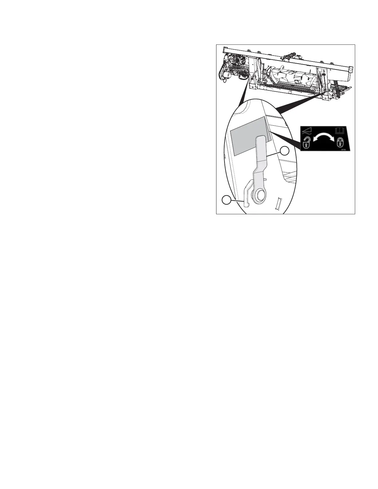
Figure 7.45: Float Lock Handle
24. Disengage the float locks by pulling each float lock
handle (A) away from the float module and setting it in
unlocked position (B).
NOTE:
Illustration at right shows the right side of the header. Float
lock on left side of header opposite.
25. Proceed to 7.7 Completing Header Assembly, page 249.
ATTACHING HEADER TO COMBINE