215184 233 Revision A
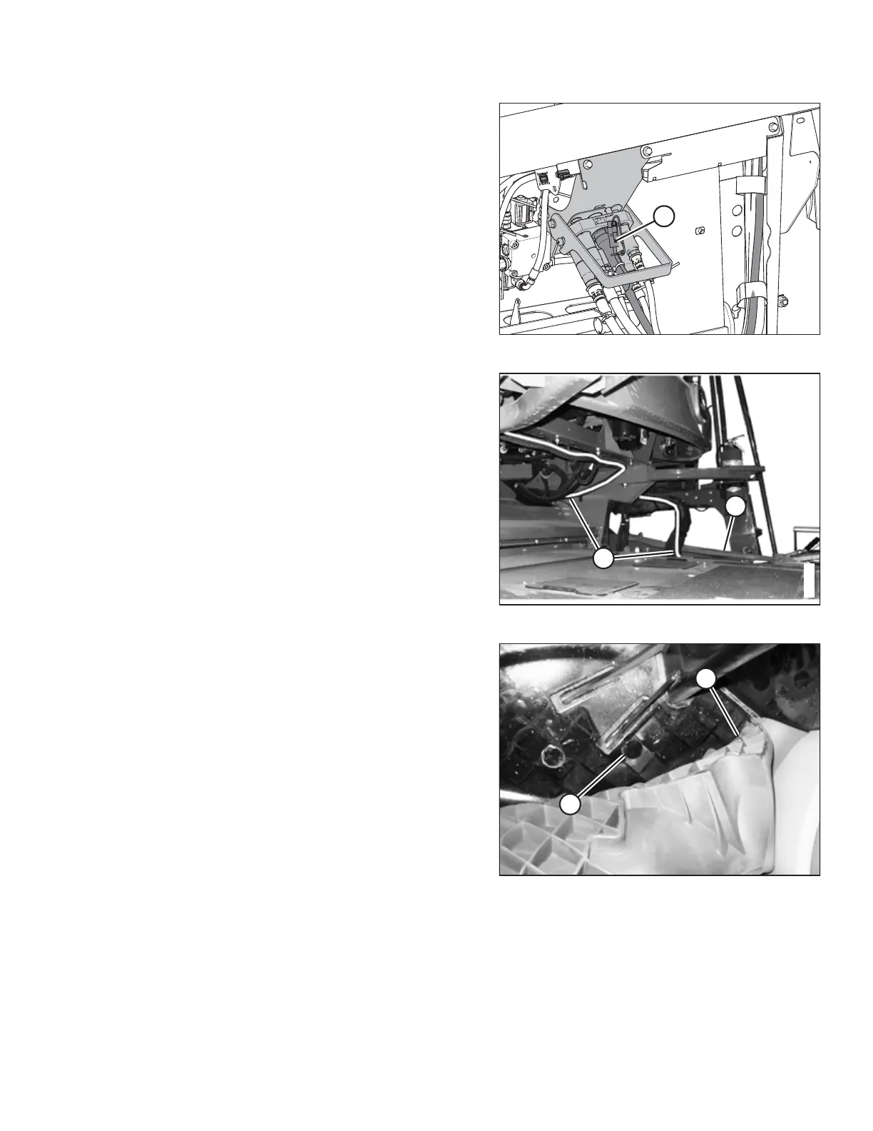
Figure 7.65: Multicoupler on Float Module
4. At the multicoupler, connect the cab draper extension
harness (MD #304211) to the float module as follows:
• Connector C3A – If the In-Cab Side Draper Speed
Control kit has been installed, plug connector C3B on
the valve drive harness into connector C3A. If the In-
Cab Side Draper Speed Control kit has not been
installed, leave C3A unconnected.
• Connector C5B – Plug connector C5B (A) into
connector C5A on the JD completion harness.
NOTE:
Connectors C3A and C5B are shipped with caps. The caps
need to be removed in order to connect these connectors.
Figure 7.66: Harness Routing
5. Route cab draper extension harness (A) along the left side
of the combine feeder house, under shield (B), to the
underside of the combine cab (along the existing hoses).
NOTE:
The illustration shows an S6, S7, T6, or T7 Series combine.
Earlier models may look different.
6. Secure cab draper extension harness (A) to the hoses with
cable ties (MD #16661) as required.
Figure 7.67: Floor Mat at Forward Right Corner and
Knockout
7. Inside the cab, lift floor mat (A) at the front right corner to
access knockout (B).
NOTE:
The illustration shows an S6, S7, T6, or T7 Series combine.
Earlier models may look different.
8. Remove knockout (B).
ATTACHING HEADER TO COMBINE