215184 412 Revision A
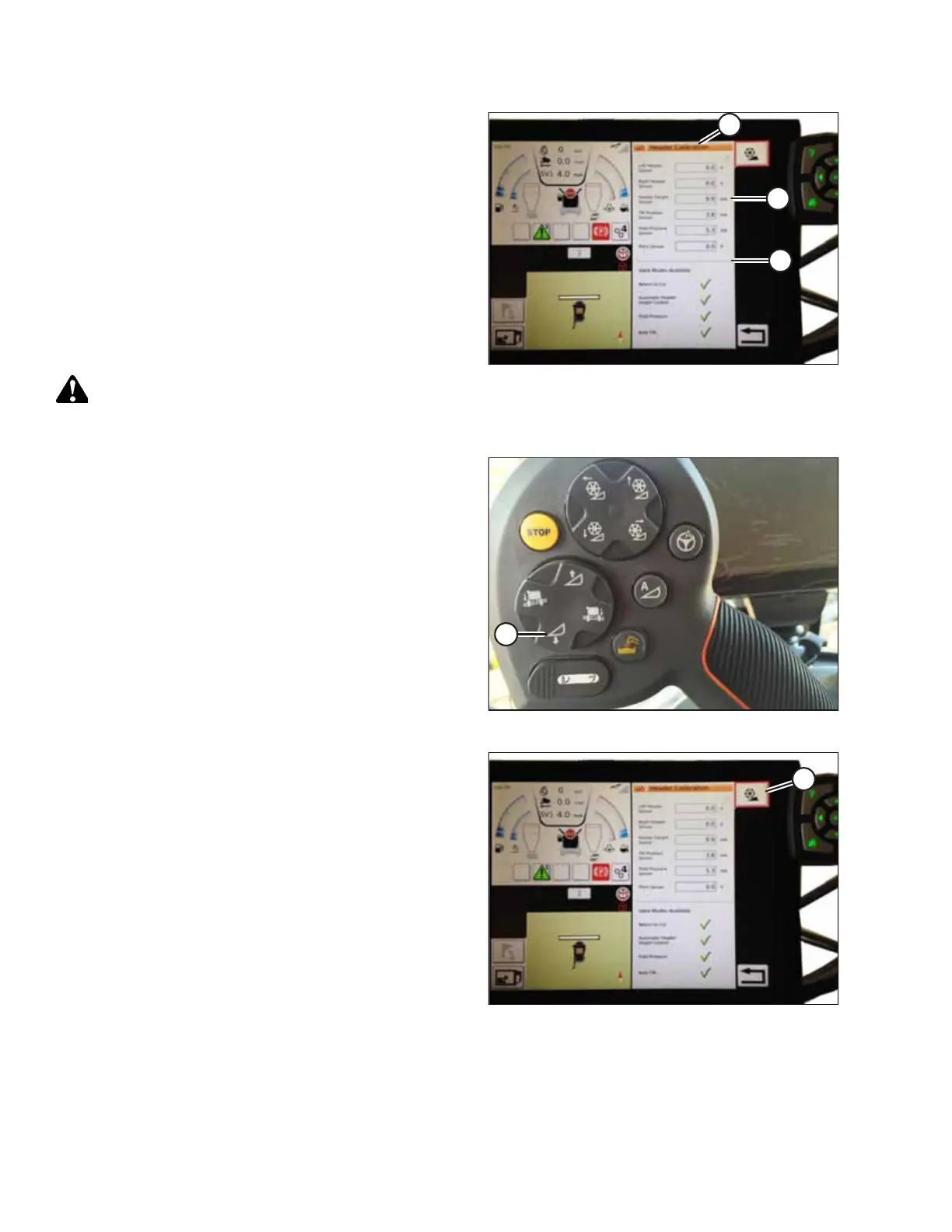
Figure 9.234: Header Calibration Page
The right side of the page shows Header Calibration
information (A). Results are shown for a variety of sensors (B):
• Left and right header sensor (voltage) (values will be the
same with MacDon headers)
• Header height sensor (mA)
• Tilt position sensor (mA)
The following valid modes are shown with check marks (C)
below sensor values (B):
• Return to cut
• Automatic header height control
WARNING
Clear the area of other persons, pets etc. Keep children away
from machinery. Walk around the machine to be sure no one is under, on, or close to it.
Figure 9.235: Header Down Switch
3. On the control handle, touch HEADER DOWN button (A).
Sensor values start changing on the HEADER CALIBRATION
page as the header lowers.
NOTE:
The header needs to be lowered all the way, and then
raised off the ground. The range should be between 0.5
and 4.5 V. If the value is not in that range, the sensor needs
to be adjusted. For instructions, refer to Adjusting Voltage
Limits – One-Sensor System, page 314 or Adjusting Voltage
Limits – Two-Sensor System, page 316.
Figure 9.236: Header Calibration
4. When the sensor values are stable, touch CALIBRATE
icon (A).
SETTING UP AUTO HEADER HEIGHT CONTROL