215184 38 Revision A
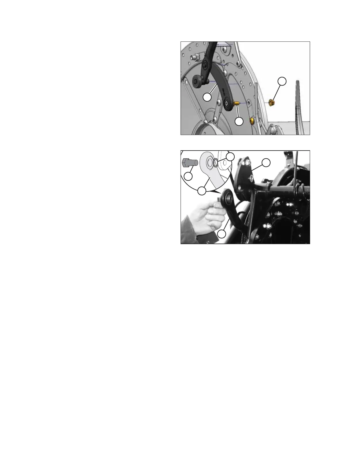
Figure 3.44: Cam Arm on Five-Bat Reel
4. Install cam arm (A) with preinstalled stud (B) into disc.
Secure with 1/2 in. smooth-face lock nut (C), and torque to
75 Nm (55 lbf·ft).
Figure 3.45: Bar Crank Attachment Holes and Link
Alignment
5. Rotate tine bar crank (A) and position link (B) so
attachment holes in bar crank are aligned with hole in link.
6. Install bolt (C) in link and position shim (D) on bolt so that
shim is BETWEEN link (B) and tine bar crank (A).
IMPORTANT:
Make sure shim (D) is installed in the correct location to
avoid damage to the bar crank.
NOTE:
Bolts are precoated with Loctite
®
, so no further locking
method is required.
7. Repeat for remaining tine bars, and then torque bolts (C) to
165 Nm (120 lbf·ft).
ASSEMBLING THE HEADER AND FLOAT MODULE