215184 48 Revision A
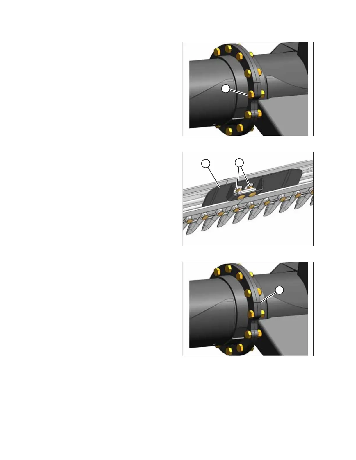
Figure 3.69: Split-Frame Joint
5. Attach backtube of split frame to backtube of header with
retained 5/8 x 1-3/4 in. long hex bolts and lock nuts (A).
Figure 3.70: Cutterbar Connector
6. Retrieve all parts from the hardware bag labelled A.
7. Position connector (A) onto cutterbar lugs (B) as shown and
install with retained 5/8 x 1-1/4 in. carriage bolts and lock
nuts. Do NOT fully tighten.
Figure 3.71: Split-Frame Joint
8. Use alignment marks (A) to align the end frame prior to
fully tightening bolts. Torque flange bolts to 271 Nm
(200 lbf·ft).
IMPORTANT:
If Grade 5 bolts are used, torque them to 203 Nm
(150 lbf·ft). Refer to 12.2 Torque Specifications, page 506
for bolt identification.
ASSEMBLING THE HEADER AND FLOAT MODULE