215184 67 Revision A
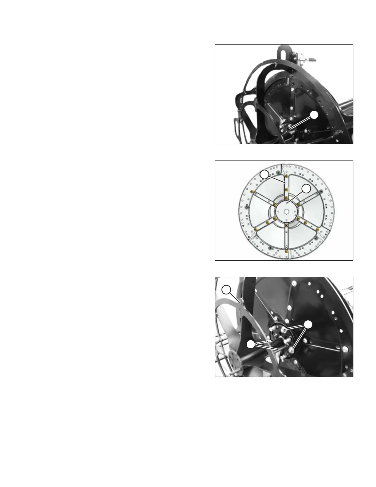
Figure 3.121: Jig and Reel Tube
3. Rotate the reel so the row of disc seam bolts that line up
with tapped hole (A) in reel tube point to the 12 o’clock
position.
Figure 3.122: Reel Position
NOTE:
Only one row (A) of disc seam bolts will line up with a tapped
hole (B) in the center mounting plate.
Figure 3.123: Jig and Reel Tube
4. Secure jig (A) to reel tube with four bolts (B) in center
flange.
ASSEMBLING THE HEADER AND FLOAT MODULE