7.4 Faults
234 SIEPCYEUOQ2V01A Q2V Technical Manual
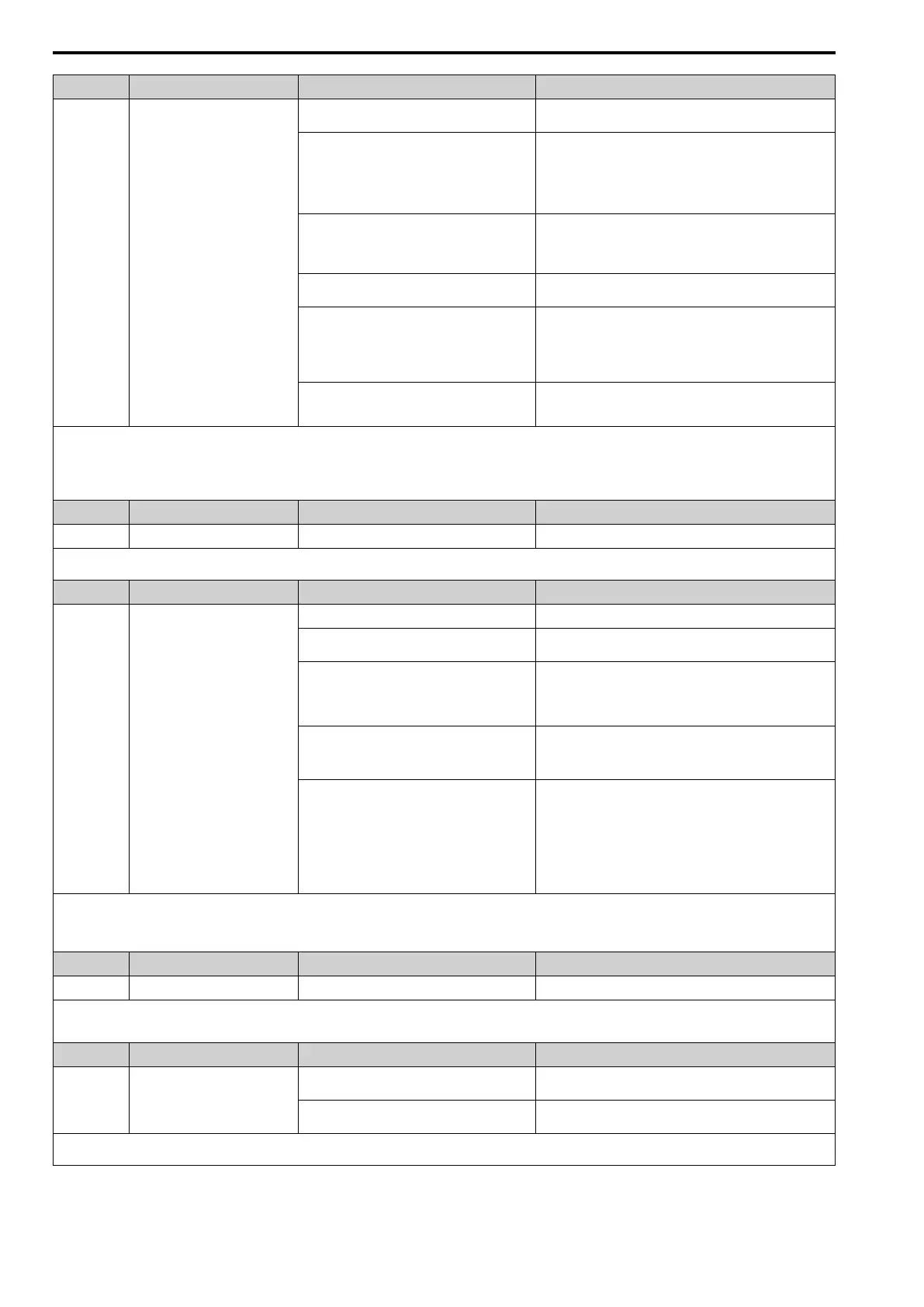
Code Name Causes Possible Solutions
The braking resistor or braking resistor unit wiring
is incorrect.
Correct wiring errors in the connection to the braking resistor or
braking resistor unit.
Electrical interference caused a drive malfunction. • Examine the control circuit lines, main circuit lines, and
ground wiring, and decrease the effects of electrical
interference.
• Make sure that a magnetic contactor is not the source of the
electrical interference, then use a Surge Protective Device if
necessary.
The load inertia is set incorrectly. • Examine the load inertia settings with KEB, overvoltage
suppression, or stall prevention during deceleration.
• Adjust L3-25 [Load Inertia Ratio] to match the qualities of the
machine.
The Short Circuit Braking function used in OLV/
PM control method.
Connect a braking resistor to the drive.
There is motor hunting. • Set n1-01 = 1 [HuntPrev Selection = Enabled] and adjust n1-
02 [HuntPrev Gain Setting].
• Adjust n2-02 [AFR Time 1] and n2-03 [AFR Time 2].
• Adjust n8-45 [SpdFbck Det.Gain] and n8-47 [Pull-In Comp.
Time Constant].
Speed search does not complete at start when you
set A1-02 = 8 [EZ Vector] and use an induction
motor.
When E9-01 = 0 [Motor Type Selection = IM], set b3-24 = 2
[SpSrch Method Selection = Current Det2].
Note:
• The drive detects this error if the DC bus voltage is more than the ov detection level while the drive is running.
• The ov detection level is approximately 410 V with 200 V class drives. The detection level is approximately 820 V for 400 V class drives.
• Do a Fault Reset to clear the fault.
• L5-08 [U/OV,OH,GF A-Reset Select] disables the Auto Restart function.
Code Name Causes Possible Solutions
PE1, PE2 PLC Faults
The communication option detected a fault. Refer to the manual for the communication option card.
Note:
Do a Fault Reset to clear the fault.
Code Name Causes Possible Solutions
PF Input Phase Loss
There is a phase loss in the drive input power. Correct errors with the wiring for main circuit drive input power.
There is loose wiring in the drive input power
terminals.
Tighten the terminal screws to the correct tightening torque.
The drive input power voltage is changing too
much.
• Examine the input power for problems.
• Make the drive input power stable.
• If the input power supply is good, examine the magnetic
contactor on the main circuit side for problems.
There is unsatisfactory balance between voltage
phases.
• Examine the input power for problems.
• Make the drive input power stable.
• Set L8-05 = 0 [In PhaseLoss Selection = Disabled].
The main circuit capacitors have become
unserviceable.
• Examine the capacitor maintenance time in monitor U4-05
[Capacitor Maintenance]. If U4-05 is more than 90%, replace
the control board or the drive. For information about replacing
the control board, contact the manufacturer or your nearest
sales representative.
• If drive input power is correct and the fault stays, replace the
control board or the drive. For information about replacing the
control board, contact the manufacturer or your nearest sales
representative.
Note:
• The drive detects this error if the DC bus voltage changes irregularly without regeneration.
• Do a Fault Reset to clear the fault.
• Use L8-05 to enable and disable PF detection.
Code Name Causes Possible Solutions
PGo Encoder (PG) Feedback Loss
The holding brake is stopping the motor. Release the holding brake.
Note:
• Do a Fault Reset to clear the fault.
• If the drive detects this error, it will operate the motor as specified by the Stopping Method set in F1-02 [PGOpen Detection Select].
Code Name Causes Possible Solutions
rF Braking Resistor Fault
The resistance of the dynamic braking option
connected to the drive is too low.
Use a dynamic braking option that fits the model and duty rating
of the drive.
A regenerative converter or regenerative unit is
connected to the drive.
Set L8-55 = 0 [DB IGBT Protection = Disable].
Note:
Do a Fault Reset to clear the fault.

 Loading...


