Troubleshooting
7
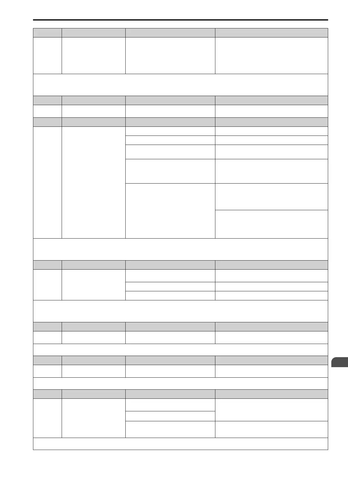
7.5 Minor Faults/Alarms
SIEPCYEUOQ2V01A Q2V Technical Manual 245
Code Name Causes Possible Solutions
Electrical interference caused a drive malfunction. • Examine the control circuit lines, main circuit lines, and
ground wiring, and decrease the effects of electrical
interference.
• Make sure that a magnetic contactor is not the source of the
electrical interference, then use a Surge Protective Device if
necessary.
• Set L5-01 ≠ 0 [Auto-Reset Attempts ≠ 0 times].
Note:
• The drive detects this error if the DC bus voltage is more than the ov detection level when the Run command has not been input (while the drive is stopped).
• The ov detection level is approximately 410 V with 200 V class drives. The detection level is approximately 820 V for 400 V class drives.
• If the drive detects this error, the terminal set to H2-01 to H2-03 = 4 [MFDO Function Select = Alarm] will activate.
Code Name Causes Possible Solutions
PASS Modbus Communication Test
The Modbus communications test is complete. The PASS display will turn off after communications test mode is
cleared.
Code Name Causes Possible Solutions
PF Input Phase Loss
There is a phase loss in the drive input power. Correct all wiring errors with the main circuit power supply.
Loose wiring in the input power terminals. Tighten the screws to the correct tightening torque.
The drive input power voltage is changing too
much.
• Examine the supply voltage for problems.
• Make the drive input power stable.
Unsatisfactory balance between voltage phases. • Examine the supply voltage for problems.
• Make the drive input power stable.
• If the supply voltage is good, examine the magnetic contactor
on the main circuit side for problems.
The main circuit capacitors have become
unserviceable.
• Examine the capacitor maintenance time in monitor U4-05
[Capacitor Maintenance].
• If U4-05 is more than 90%, replace the capacitor. Contact the
manufacturer or your nearest sales representative for more
information.
• Examine the supply voltage for problems.
• Re-energize the drive.
• If the alarm stays, replace the circuit board or the drive. For
information about replacing the control board, contact the
manufacturer or your nearest sales representative.
Note:
• The drive detects this error if the DC bus voltage changes irregularly without regeneration.
• If the drive detects this error, the terminal assigned to H2-01 to H2-03 = 4 [MFDO Function Select = Alarm] will be ON.
• Use L8-05 [In PhaseLoss Selection] to enable and disable PF detection.
Code Name Causes Possible Solutions
PGo Encoder (PG) Feedback Loss
The encoder cable is disconnected or wired
incorrectly.
Examine for wiring errors or disconnected wires in the encoder
cable, and repair problems.
The encoder is not receiving power. Examine the encoder power supply.
The holding brake is stopping the motor. Release the holding brake.
Note:
• The drive detects this error if it does not receive the speed detection pulse signal from the encoder in the detection time set in F1-14 [Encoder Open-Circuit Detect Time].
• If the drive detects this error, the terminal assigned to H2-01 to H2-03 = 4 [MFDO Function Select = Alarm] will activate.
• If the drive detects this error, it will operate the motor as specified by the stopping method set in F1-02 [PGOpen Detection Select].
Code Name Causes Possible Solutions
rUn Motor Switch during Run
The drive received a Motor 2 Select [H1-xx = 61]
during run.
Make sure that the drive receives the Motor 2 Selection while the
drive is stopped.
Note:
If the drive detects this error, the terminal set to H2-01 to H2-03 = 4 [MFDO Function Select = Alarm] will activate.
Code Name Causes Possible Solutions
SE Modbus Test Mode Error
Modbus communications self-diagnostics [H1-xx =
7F] was done while the drive was running.
Stop the drive and do Modbus communications self-diagnostics.
Note:
If the drive detects this error, the terminal set to H2-01 to H2-03 = 4 [MFDO Function Select = Alarm] will activate.
Code Name Causes Possible Solutions
SToF Safe Torque OFF Failure
One of the two terminals H1-HC and H2-HC
received the Safe Disable input signal.
The Safe Disable input signal is wired incorrectly.
• Make sure that the Safe Disable signal is input from an
external source to terminals H1-HC or H2-HC.
• When the Safe Disable function is not in use, connect
terminals H1-HC and H2-HC.
There is internal damage to one Safe Disable
channel.
Replace the board or the drive. For information about replacing
the control board, contact the manufacturer or your nearest sales
representative.
Note:
If the drive detects this error, the terminal assigned to H2-01 to H2-03 = 4 [MFDO Function Select = Alarm] will be ON.

 Loading...


