Parameter List
11
11.9 H: TERMINALS
SIEPCYEUOQ2V01A Q2V Technical Manual 359
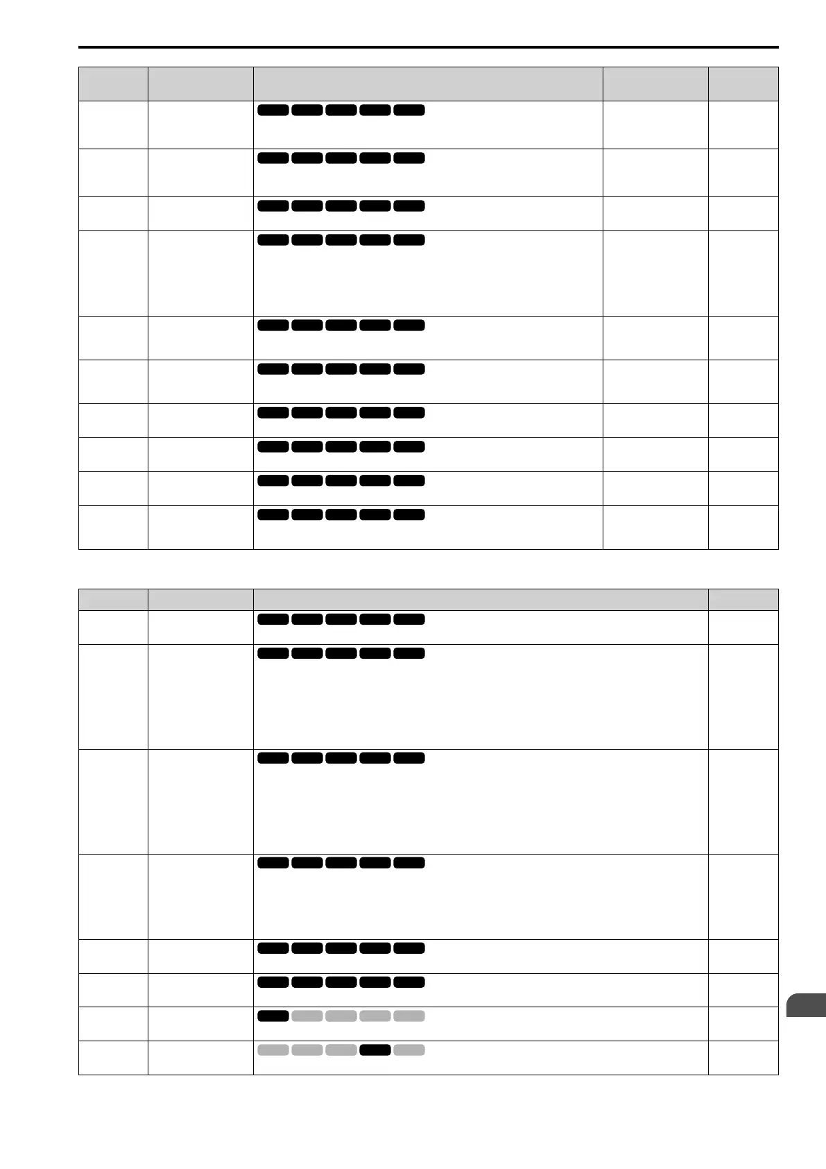
No.
(Hex.)
Name Description
Default
(Range)
Ref.
H3-11
(0419)
RUN
AI2 Gain Setting
Sets the gain of the analog signal input to MFAI terminal AI2.
100.0%
(-999.9 - +999.9%)
611
H3-12
(041A)
RUN
AI2 Bias Setting
Sets the bias of the analog signal input to MFAI terminal AI2.
0.0%
(-999.9 - +999.9%)
611
H3-13
(041B)
An.In FilterTime
Constant
Sets the time constant for primary delay filters on MFAI terminals.
0.03 s
(0.00 - 2.00 s)
611
H3-14
(041C)
An.In Term.Enable Sel
Sets the enabled terminal or terminals when H1-xx = 12 [MFDI Function Select = AI
Input Sel] is ON.
1 : AI1 only
2 : AI2 only
3 : AI1 and AI2
3
(1, 2, 3)
612
H3-16
(02F0)
AI1 Offset
Sets the offset level for analog signals input to terminal AI1. Usually it is not necessary
to change this setting.
0
(-500 - +500)
612
H3-17
(02F1)
AI2 Offset
Sets the offset level for analog signals input to terminal AI2. Usually it is not necessary
to change this setting.
0
(-500 - +500)
612
H3-40
(0B5C)
15C1h Input Function
Sets the Modbus AI1 function.
0
(0, 3, 6 - 2F)
612
H3-41
(0B5F)
15C2h Input Function
Sets the Modbus AI2 function.
0
(0, 3, 6 - 2F)
612
H3-42
(0B62)
15C3h Input Function
Sets the Modbus AI3 function.
0
(0, 3, 6 - 2F)
613
H3-43
(117F)
Mbus In FilterTime
Const
Sets the time constant to apply a primary delay filter to the Modbus analog input
terminal.
0.00 s
(0.00 - 2.00 s)
613
■ H3-xx: MFAI Function Select
Setting Value Function Description Ref.
0 Through Mode
Use this setting for unused terminals or to use terminals in through mode.
613
1 AuxFreqRef1
Sets Reference 2 through multi-step speed reference to enable the command reference (Auxiliary Frequency
Reference 1) from the analog input terminal set here. This value is a percentage where the Maximum Output
Frequency setting is a setting value of 100%.
Note:
Parameter A1-02 [Control Method] selects which parameter is the maximum output frequency.
• A1-02 ≠ 8 [EZ Vector]: E1-04 [Max Output Frequency]
• A1-02 = 8: E9-02 [Maximum Speed]
613
2 AuxFreqRef2
Sets Reference 3 through multi-step speed reference to enable the command reference (Auxiliary Frequency
Reference 2) from the analog input terminal set here. This value is a percentage where the Maximum Output
Frequency setting is a setting value of 100%.
Note:
Parameter A1-02 [Control Method] selects which parameter is the maximum output frequency.
• A1-02 ≠ 8 [EZ Vector]: E1-04 [Max Output Frequency]
• A1-02 = 8: E9-02 [Maximum Speed]
613
3 FrqBIAS Frq
Enters the bias value added to the frequency reference as a percentage of the maximum output frequency.
Note:
Parameter A1-02 [Control Method] selects which parameter is the maximum output frequency.
• A1-02 ≠ 8 [EZ Vector]: E1-04 [Max Output Frequency]
• A1-02 = 8: E9-02 [Maximum Speed]
613
4 Freq Ref/BIAS
The input value from the MFAI terminal set with this function becomes the master frequency reference.
613
5 Freq Gain
The drive multiplies the analog frequency reference with the input value from the MFAI set with this function.
614
6 Output Voltage Bias
Set this parameter to input a bias signal to amplify the output voltage.
614
7 TorqCompensation
Enters the torque compensation value if the motor rated torque is 100%.
614

 Loading...


