Electrical Installation
3
3.2 Standard Connection Diagram
SIEPCYEUOQ2V01A Q2V Technical Manual 43
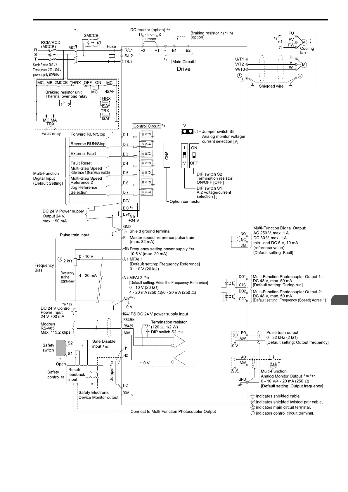
Figure 3.1 Standard Drive Connection Diagram
*1 Set the wiring sequence to de-energize the drive with the MFDO. If the drive outputs a fault during fault restart when you use the
fault restart function, set L5-02 = 2 [Fault@Reset Select = Enable Fault Output] to de-energize the drive. Be careful when you use a
cut-off sequence. The default setting for L5-02 is 1 [Disable Fault Output].
*2 When you install a DC reactor, you must remove the jumper between terminals +1 and +2.

 Loading...


