12.3 C: TUNING
500 SIEPCYEUOQ2V01A Q2V Technical Manual
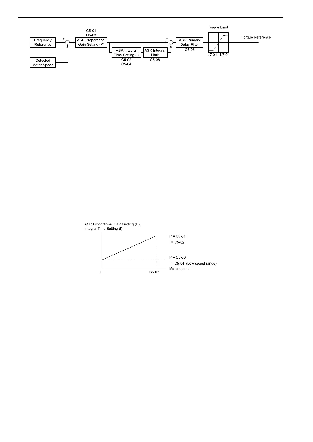
Figure 12.44 Speed Control Block Diagram for AOLV/PM and EZOLV
Note:
The detected speed is the speed estimation value when configured such that A1-02 = 6 or 8 [PM AOLVector = PM AOLVector or EZ
Vector].
■ Before You Adjust ASR Parameters
• Do Auto-Tuning and set up all motor data correctly.
• Always make adjustments with the load connected to the motor.
• Use analog output signals to monitor U1-16 [SFS Output Frequency] and U1-05 [Motor Speed] when you
adjust the ASR.
■ ASR Adjustment Procedure for AOLV/PM and EZOLV
Do this procedure to adjust ASR parameters:
1. Run the motor at zero speed or low speed and increase C5-01 [ASR PGain 1] until immediately before
vibration starts to occur.
2. Run the motor at zero speed or low speed and decrease C5-02 [ASR ITime 1] until immediately before
vibration starts to occur.
3. Check for oscillation when you run the motor at maximum speed.
4. If oscillation occurs, increase C5-02 and decrease C5-01.
When there is no oscillation, the adjustment procedure is complete.
5. Set the low-speed gain. Run the motor at zero speed or low speed and increase C5-03 [ASR PGain 2] until
immediately before vibration starts to occur.
Figure 12.45 Low-speed/High-speed Gain Settings
6. Set the low-speed integral time. Run the motor at zero speed or low speed and decrease C5-04 [ASR ITime 2]
until immediately before vibration starts to occur.
7. Set C5-07 [ASR Gain Switch Frequency].
8. Check for oscillation when you run the motor at speeds more than the setting in C5-07.
Note:
• If overshooting occurs when acceleration ends, decrease the value set in C5-01 and increase the value set in C5-02.
• If undershoot occurs at stop, decrease C5-03 and increase C5-04.
■ Use MFDI Switch for Proportional Gain
You can use the input terminals set for ASR Gain (C5-03) Select [H1-xx = 45] to switch the proportional gains set
with C5-01 and C5-03. When the configured input terminal is deactivated, the proportional gain set for C5-01 is
selected. When the terminal is activated, the proportional gain set for C5-03 is selected. The proportional gain
changes linearly over the time set in C5-02 [ASR ITime 1]. The signals from this MFDI are more important than
C5-07 [ASR Gain Switch Frequency].

 Loading...


