12.7 H: TERMINALS
588 SIEPCYEUOQ2V01A Q2V Technical Manual
■ Extend MFDO1 to MFDO3 Function Selection
You can set MFDO functions to bit 0 to bit 2 [Mbus MFDO1 to 3] of Modbus register 15E0 (Hex.). Use H2-40 to
H2-42 [Mbus 15E0h b0 Output Function to Mbus 15E0h b2 Output Function] to select the function.
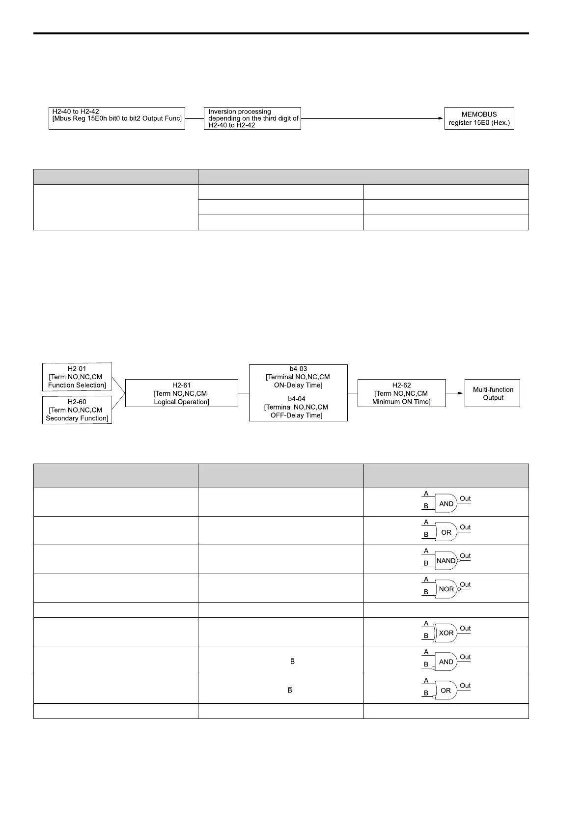
Figure 12.73 Functional Block Diagram of Modbus Multi-function Output
Table 12.45 Modbus MFDO Registers
Register No. (Hex.) Name
15E0
bit0 Mbus MFDO 1
bit1 Mbus MFDO 2
bit2 Mbus MFDO 3
Note:
• Refer to H2: DIGITAL OUTPUTS on page 587 for more information about MFDO setting values.
• When you do not set functions to H2-40 to H2-42, set them to 0.
■ Output of Logical Operation Results of MFDO
This enables the logical operation results of two MFDOs to be output to one MFDO terminal.
Use H2-60, H2-63, and H2-66 [NO,NC,CM 2nd Function, DO1 2nd Function, and DO2 2nd Function] to set the
function of the output signal for which you will perform logical operations.
Use H2-61, H2-64, and H2-67 [NO,NC,CM Logic Operation, DO1 Logic Operation, and DO2 Logic Operation]
to set the logical operation.
Figure 12.74 Functional Block Diagram of Logical Operation Output for MFDO 1
Table 12.46 MFDO Logical Operation Table
Logical Operation Selection
H2-61, H2-64, H2-67
Logical Operation Expression Logical Operation Notation
1 A=B=1
2 A=1 or B=1
3 A=0 or B=0
4 A=B=0
5 A=B A=B
6 A != B
7
AND(A, )
8
OR(A, )
9 - On
Note:
• If you use the function to output logical calculation results, you cannot set H2-01 to H2-03 = 1xx [Inverse Output of xx]. If you do, the
drive will detect oPE33 [Digital Output Selection Error].
• When you do not use H2-60, H2-63, and H2-66, set them to 0. The through mode function is not supported.

 Loading...


