Parameter Details
12
12.10 o: KEYPAD
SIEPCYEUOQ2V01A Q2V Technical Manual 695
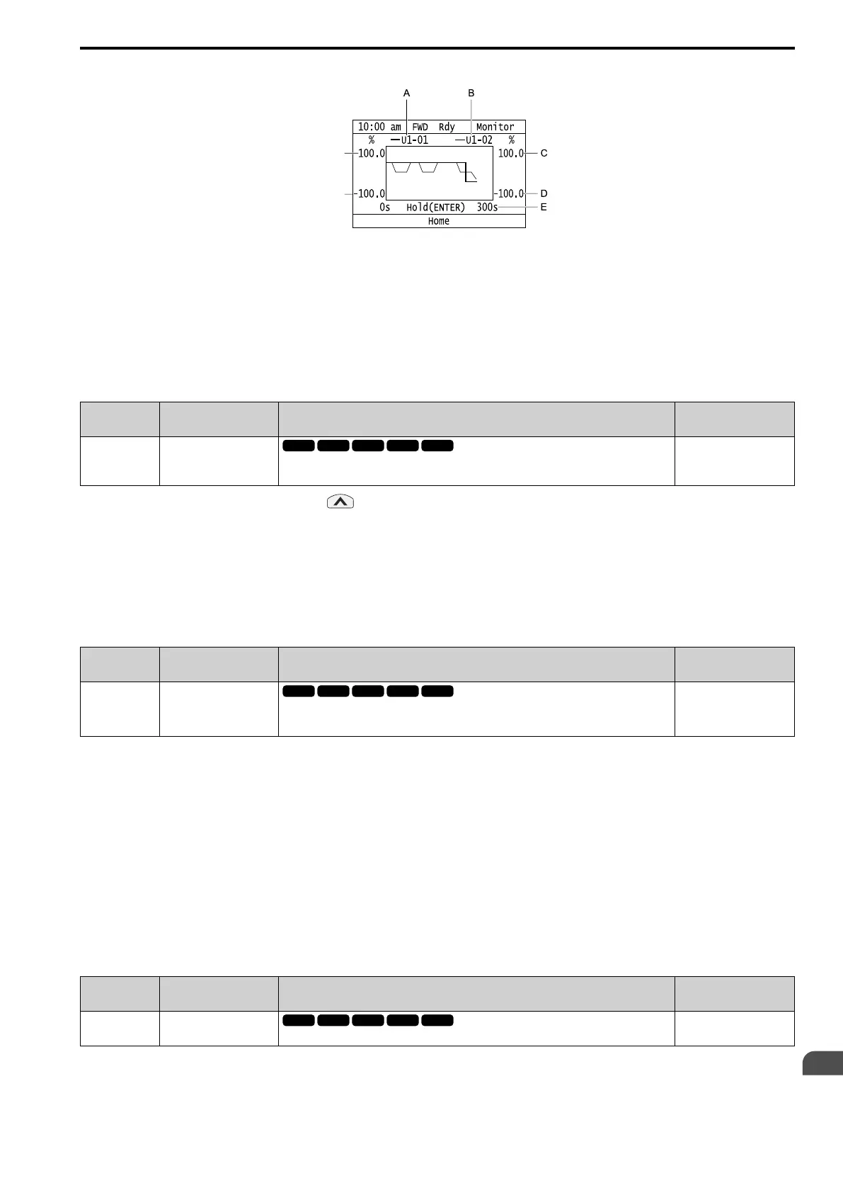
Trend Plot Display
A - Select Ux-xx [Monitors] (Monitor
1) with o1-24.
B - Select Ux-xx [Monitors] (Monitor
2) with o1-25.
C - Set the maximum value of
Monitor 2 with o1-50
D - Set the minimum value of Monitor
2 with o1-49
E - Set the time scale with o1-51
F - Set the minimum value of Monitor
1 with o1-47
G - Set the maximum value of
Monitor 1 with o1-48
■ o1-01: User Monitor Selection
No.
(Hex.)
Name Description
Default
(Range)
o1-01
(0500)
RUN
User Monitor Selection
Sets the U: MONITORS for the Drive Mode. This parameter is only available when you use an
LED keypad.
106
(104 - 855)
When the drive is in Drive Mode, push on the keypad to cycle through this data: frequency reference →
rotational direction → output frequency → output current → o1-01 selection.
Set the x-xx part of Ux-xx that is shown in the fifth position in Drive Mode. For example, to show U1-05 [Motor
Speed], set o1-01 = 105.
Note:
The monitors that you can select are different for different control methods.
■ o1-02: Mon.Sel@Power-Up
No.
(Hex.)
Name Description
Default
(Range)
o1-02
(0501)
RUN
Mon.Sel@Power-Up
Sets the monitor item that the keypad screen shows after energizing the drive. Refer to “U:
MONITORS” for information about the monitor items that the keypad screen can show. This
parameter is only available when you use an LED keypad.
1
(1 - 5)
1 : FreqReference (U1-01)
2 : Direction
3 : OutFrequency (U1-02)
4 : OutCurrent (U1-03)
5 : User Monitor (o1-01)
Shows the monitor item selected in o1-01 [User Monitor Selection].
■ o1-03: FrqDisplay Unit Selection
No.
(Hex.)
Name Description
Default
(Setting Range)
o1-03
(0502)
FrqDisplay Unit Selection
Sets the display units for the frequency reference and output frequency.
Determined by A1-02
(0 - 3)

 Loading...


