2 - 47
2 Design
High-function General-purpose Inverter RX2 Series User’s Manual
2-3 Wiring
2
2-3-4 Wiring for Main Circuit Terminals
Installing Magnetic Contactor
To shut off the main circuit power supply with a sequence, you can use a magnetic contactor (MC)
on the inverter side closer than a molded case circuit-breaker (MCCB).
However, do not run or stop the inverter by turning ON/OFF a magnetic contactor established at the
input and output side of power supply of inverter. Otherwise, it may cause damage on the inverter.
Use the RUN command signal (FW/RV) via the control circuit terminal of the inverter.
• Construct a sequence that turns OFF the power supply via the alarm output signal of the inverter.
• To use one or more braking resistors/regenerative braking units, construct a sequence that turns
OFF a magnetic contactor via a thermal relay contact in each unit.
Precautions for Correct Use
Do not shut off the power supply more than once in 3 minutes. Doing so may result in inverter
damage.
Inrush Current Flow When the Inverter Power Supply Is Turned ON
When the inverter power supply is turned ON, the charging current, which is called inrush current,
flows in the main circuit board capacitor.
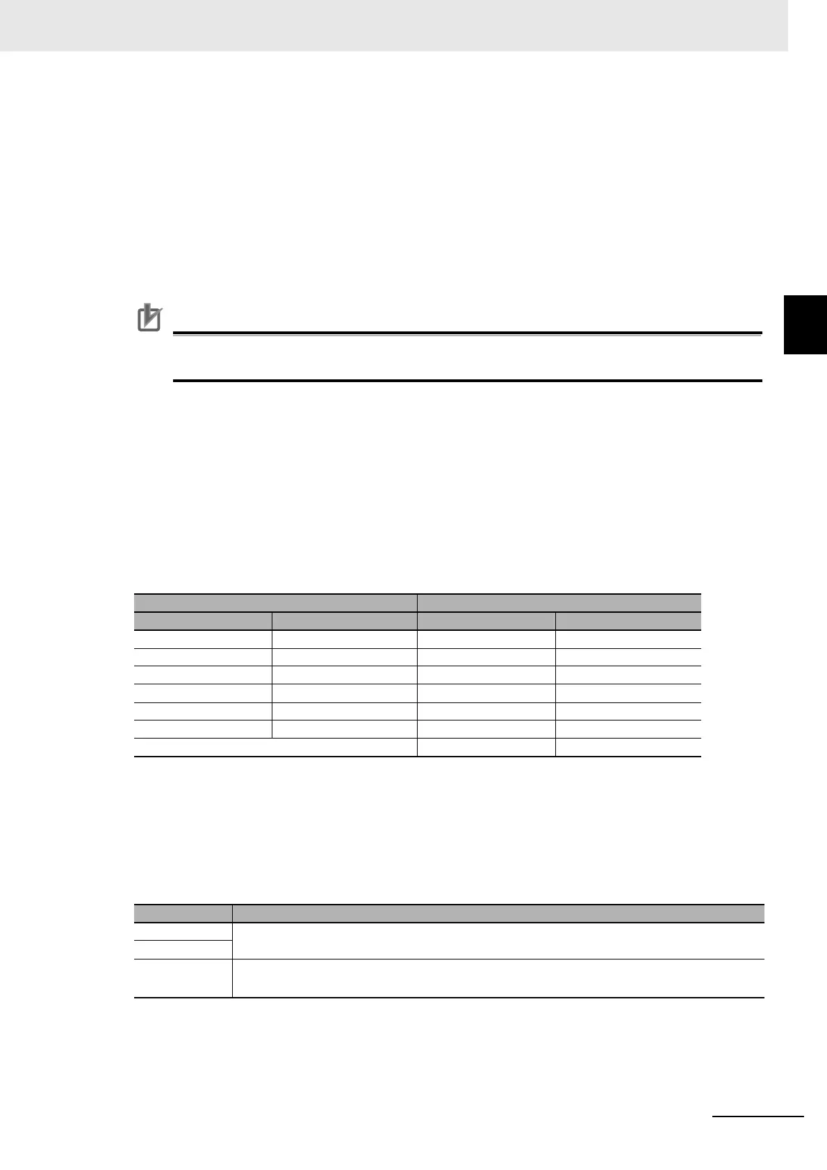
The table below shows the reference values at a power supply voltage of 240 V or 480 V when the
power supply impedance is low. Take this into consideration when selecting the inverter power sup-
ply.
• With a low-speed no-fuse breaker, an inrush current 10 times the rated current can flow for 20 ms.
• To turn ON the power supply for multiple inverters simultaneously, select a no-fuse breaker with a
20-ms allowable current greater than the total inrush current shown in the following table.
Main Power Supply Phase Loss and Single-phase Input
This inverter is designed for 3-phase power supply input. It cannot be used with a single-phase
power supply. Similarly, do not use the inverter in an input phase lost state of the 3-phase power
supply. Doing so may result in inverter damage.
Be sure to check the wiring for the 3-phase power supply before using the inverter. Note that the
inverter operates without detecting a phase loss if it occurs in the phase S as shown below.
Three-phase 200 V Level Three-phase 400 V Level
3G3RX2- Inrush Current (Ao-P) 3G3RX2- Inrush Current (Ao-P)
A2004-A2007 24 A4007-A4037 23
A2015-A2037 17 A4055-A4110 34
A2055-A2110 45 A4150-A4220 68
A2150-A2220 89 A4300-A4370 39
A2300 54 A4450-A4550 65
A2370-A2550 96 A4750-A4950 130
A411K-A413K 260
Phase loss State
Phase R
The inverter does not operate.
Phase T
Phase S
The inverter operates in a single-phase.
Under voltage or over current could occur, which could lead to the inverter broken.
 Loading...


