12 - 23
12 Troubleshooting
High-function General-purpose Inverter RX2 Series User’s Manual
12-3 Alarm Display and Its Measures
12
12-3-1 Checking Alarm Display
12-3 Alarm Display and Its Measures
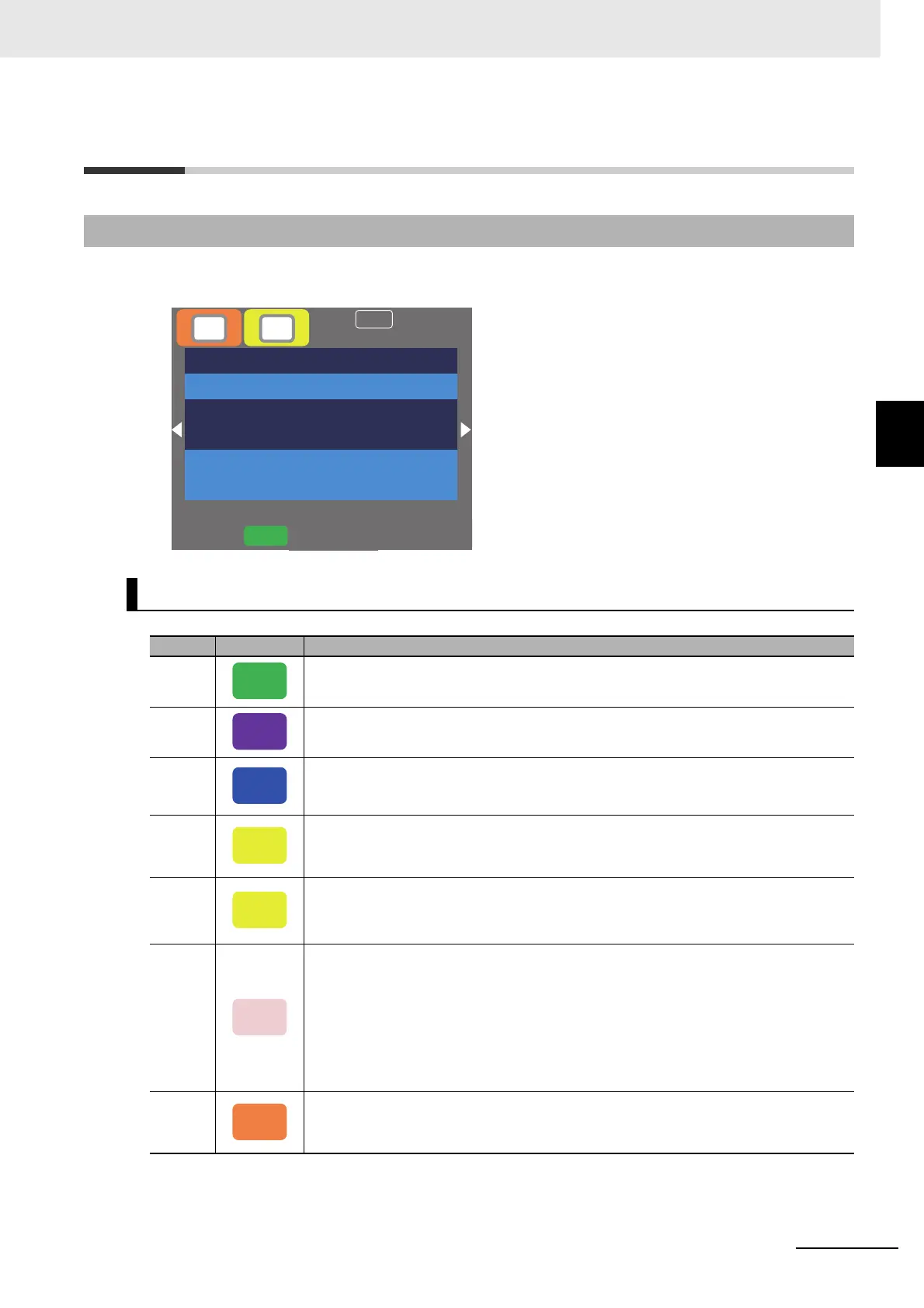
The status of the inverter is shown in the following table for LCD operator.
12-3-1 Checking Alarm Display
Indication (A) Main Operating Status Display
No. Indication Description
A1
Icon shown during normal rotation operation. Some parameters cannot be changed
while the inverter is running.
A2
Icon shown during reverse rotation operation. Some parameters cannot be changed
while the inverter is running.
A3
Icon shown during outputting under a zero-Hz command. It is also shown while DB,
FOC, SON function is working. Some parameters cannot be changed while the inverter
is running.
A4
Icon shown when an error occurred and the inverter is in trip state. Releasable errors
can be released by a reset operation.
12-1 Checking Alarm Display on page 12-2
A5
Icon shown when a setting inconsistency exists.
Eliminate the inconsistency.
12-3-2 Checking Inconsistent Settings on page 12-29
A6
Icon shown while the inverter is forced stop by the following functions although opera-
tion command is entered.
• An operation command was entered under 0Hz frequency command.
• Operation command was entered from a source other than the operation keypad and
the operation was stopped with STOP key on the operation keypad.
• The inverter stops by instantaneous power failure non-stop function.
RUN lamp flashes during this.
A7
Inverter is stopped because no operation command is given.
The inverter cannot be operated if the input terminal functions such as [RS] and [FRS]
or the STO function is ON.
Menu
Option
0.00Hz
oFW
STOP
M1
H03
Output Frequency
0.00 Hz
FA-01
Main speed command (Operator keypad)
0.00 Hz
[0.00-60.00]
NRDY
(A) (B)
RUN
RV
RUN
0Hz
TRIP
WARN
STOP
STOP

 Loading...


