B - 5
Appendices B STO Function
High-function General-purpose Inverter RX2 Series User’s Manual
B-2 Procedure for Use of STO Function
B
B-2-1 STO Signal Input
B-2 Procedure for Use of STO Function
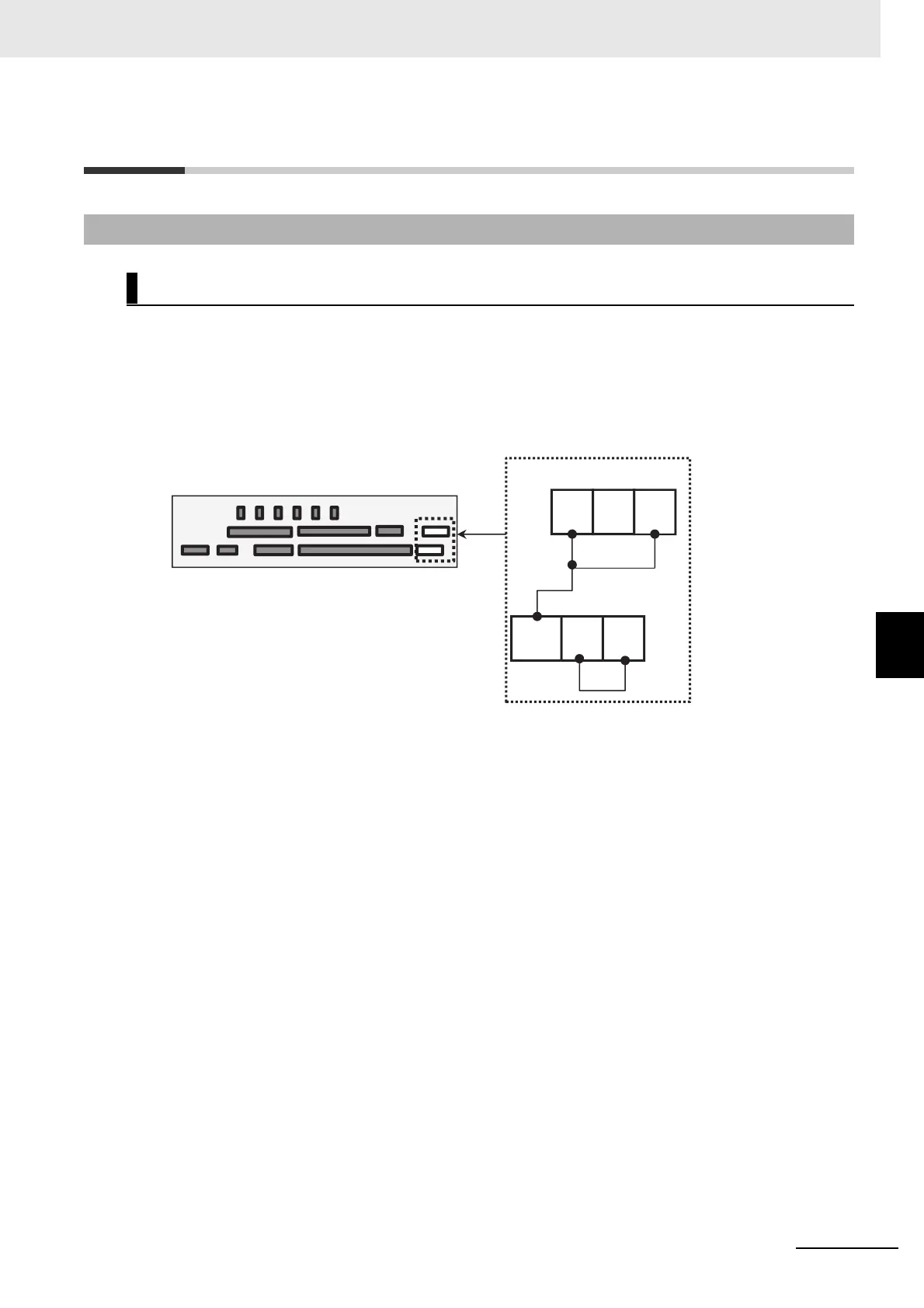
Input of STO signal is performed by redundant input of STO terminals ST1 and ST2.
When voltage is applied to each input terminal and current flows, operation of safety path is enabled.
When shipped from the factory, the operation status is always enabled with short circuit wiring shown
as below.
If voltage is not applied to at least one of the input terminals, the corresponding blocking path shuts off
output of the inverter.
B-2-1 STO Signal Input
STO Input Terminal
Control circuit terminal area
Source logic inverter
model
STO input