9 - 21
9 Communications Functions
High-function General-purpose Inverter RX2 Series User’s Manual
9-5 Modbus Communication Register Number List
9
9-5-1 Coil Number List
9-5 Modbus Communication Register
Number List
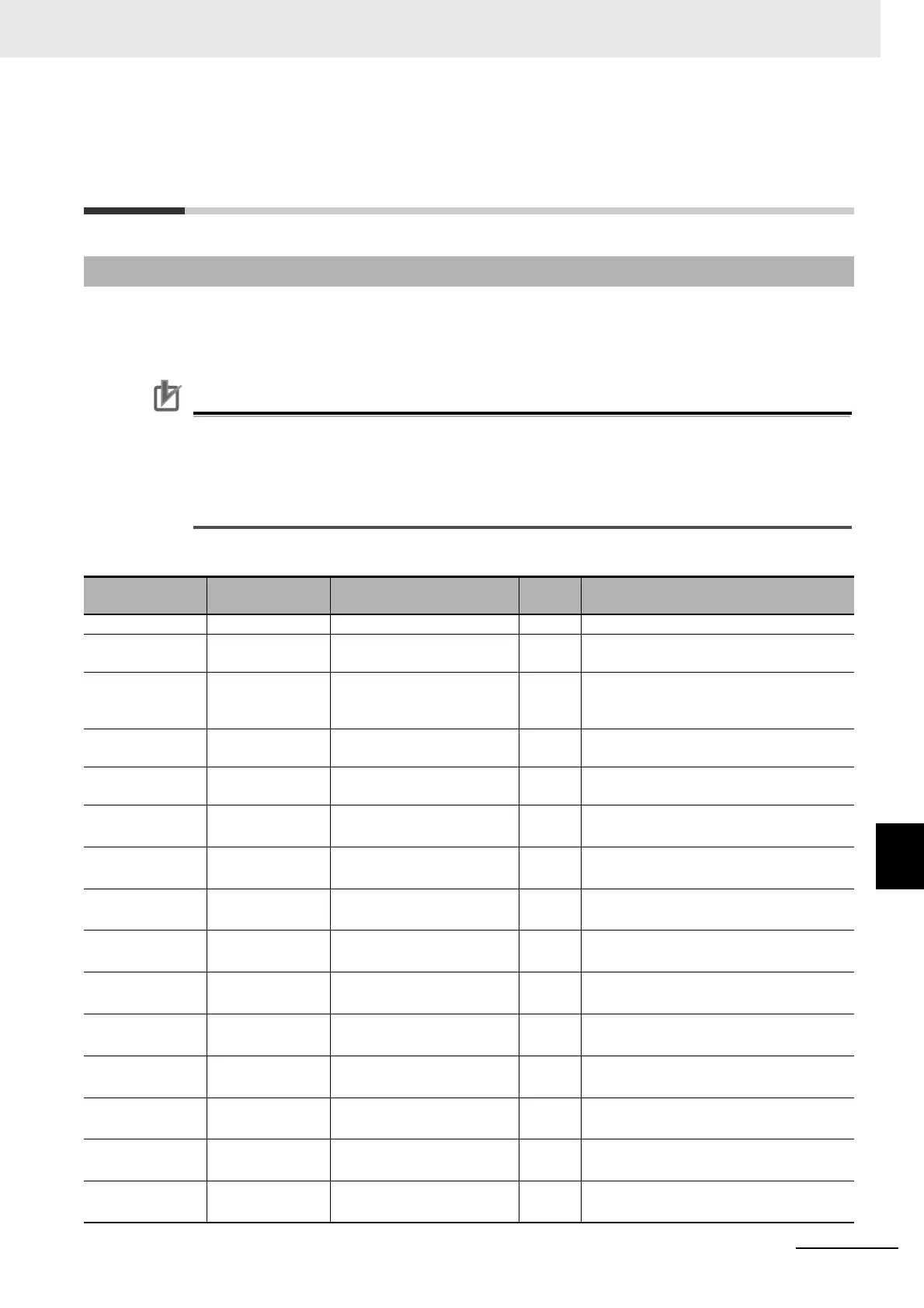
R/W in the list shows whether data can be read from, or written to, the coil or holding register.
R: Read only
R/W: Read and Write enabled
Precautions for Correct UsePrecautions for Correct Use
• The “Coil No.” in the table header shows the coil number used inside the inverter.
• The “Modbus coil spec. No.” in the table header shows the coil number used to actually spec-
ify the coil in the Modbus communication process.
This coil number is 1 less than the inverter “Coil No.” according to the Modbus communica-
tion specifications.
Coil Number List
9-5-1 Coil Number List
Coil No.
Modbus coil
spec. No.
Item R/W Description
0000h (Reserved)
0001h 0000h Operation command R/W
1: Run
0: Stop (enabled when AA111/AA211=03)
0002h 0001h Rotation direction command R/W
1: Reverse
0: Normal (enabled when AA111/
AA211=03)
0003h 0002h External trip [EXT] R/W
1: Trip
0: Not trip
0004h 0003h Trip reset [RS] R/W
1: Reset
0: Not reset
0005h 0004h Input terminal 1 R/W
1: ON
0: OFF
*1
0006h 0005h Input terminal 2 R/W
1: ON
0: OFF
*1
0007h 0006h Input terminal 3 R/W
1: ON
0: OFF
*1
0008h 0007h Input terminal 4 R/W
1: ON
0: OFF
*1
0009h 0008h Input terminal 5 R/W
1: ON
0: OFF
*1
000Ah 0009h Input terminal 6 R/W
1: ON
0: OFF
*1
000Bh 000Ah Input terminal 7 R/W
1: ON
0: OFF
*1
000Ch 000Bh Input terminal 8 R/W
1: ON
0: OFF
*1
000Dh 000Ch Input terminal 9 R/W
1: ON
0: OFF
*1
000Eh 000Dh Input terminal A R/W
1: ON
0: OFF
*1