8 Applied Settings
8 - 132
High-function General-purpose Inverter RX2 Series User’s Manual
Assign the output terminal function 021 [UV] undervoltage signal to one of [CC-01] to [CC-07] that cor-
responds to the output terminal and output the signal.
The undervoltage signal can be output when a power failure occurs in the main power and control
power.
You can output the signal by assigning the undervoltage signal 021 [UV] to the output terminal
selection.
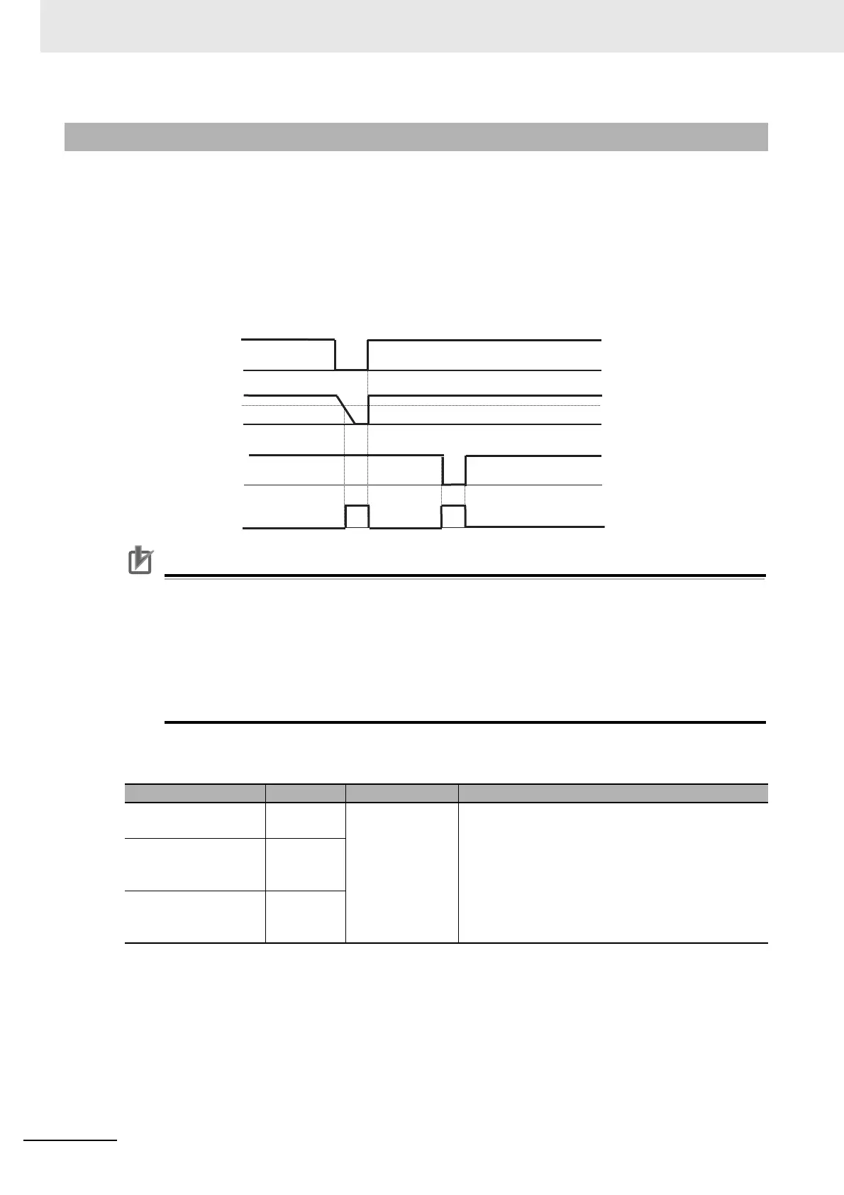
Example of an undervoltage (R0 and T0/24V are supplied from a separate power)
Precautions for Correct Use
• The undervoltage signal [UV] is output while the control power of the inverter remains (includ-
ing when a 24-V power supply is used).
• To set errors that will be generated when an undervoltage occurs, refer to 8-3-6 Instanta-
neous Power Interruption/Undervoltage Detection on page 8-72.
• To perform retry restart operation without generating errors when an undervoltage occurs,
refer to 8-2-6 Restart during Power Interruption/Undervoltage on page 8-52.
• The [UV] signal is output under an undervoltage state irrespective of the occurrence of a trip.
Parameter
8-6-7 Signal during Undervoltage (UV)
Item Parameter Data Description
Output terminal func-
tion selection 11-15
[CC-01] to
[CC-05]
021
The undervoltage signal [UV] is output.
OFF: Internal PN voltage and control power have
been established.
ON: Internal PN voltage or control power is insuffi-
cient.
Relay output terminal
function selection
16A-16C
[CC-06]
Relay output terminal
function selection
AL1-AL0/AL2-AL0
[CC-07]
Main power R-S-T
P-N voltage
R0, T0 voltage
Output signal
[UV]