6 Basic Parameter Settings
6 - 28
High-function General-purpose Inverter RX2 Series User’s Manual
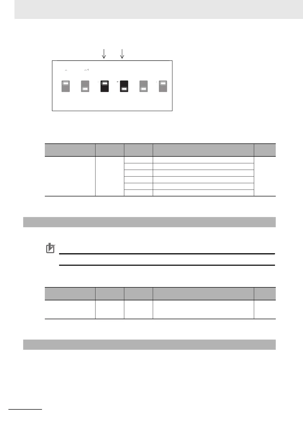
First, the voltage SW and current SW are switched when the wiring is made.
Next, a command destination for the parameter [AA101] is set.
Parameter
RS485 communication is used to give a frequency command.
Precautions for Correct Use
For details, see 9-1 Communication Specifications on page 9-2
Parameter
Frequency command is given with a pulse string input.
Note To give a pulse string input, there are two methods. One is to use the main body’s terminals and the other is
to use the PG option unit.
Item
Parameters
Data Description
Default
data
Main speed input
source selection,
1st-motor
[AA101]
01 Input between Ai1 and L enabled.
01
*1
*1. Default data when default data selection (UB-02) is set to 01.
02 Input between Ai2 and L enabled.
03 Input between Ai3 and L enabled.
04 Reserved
05 Reserved
06 Reserved
6-4-4 Case where Command Is Given through RS485 Communications
Item
Parameters
Data Description
Default
data
Main speed input
source selection,
1st-motor
[AA101] 08 Command from RS485 communication
01
*1
*1. Default data when default data selection (UB-02) is set to 01.
6-4-5 Case where Command Is Given through Input of Pulse String
((SW4) ((SW3) ((SW2) ((SW1) ((SW5) ((SW6)