2 Design
2 - 22
High-function General-purpose Inverter RX2 Series User’s Manual
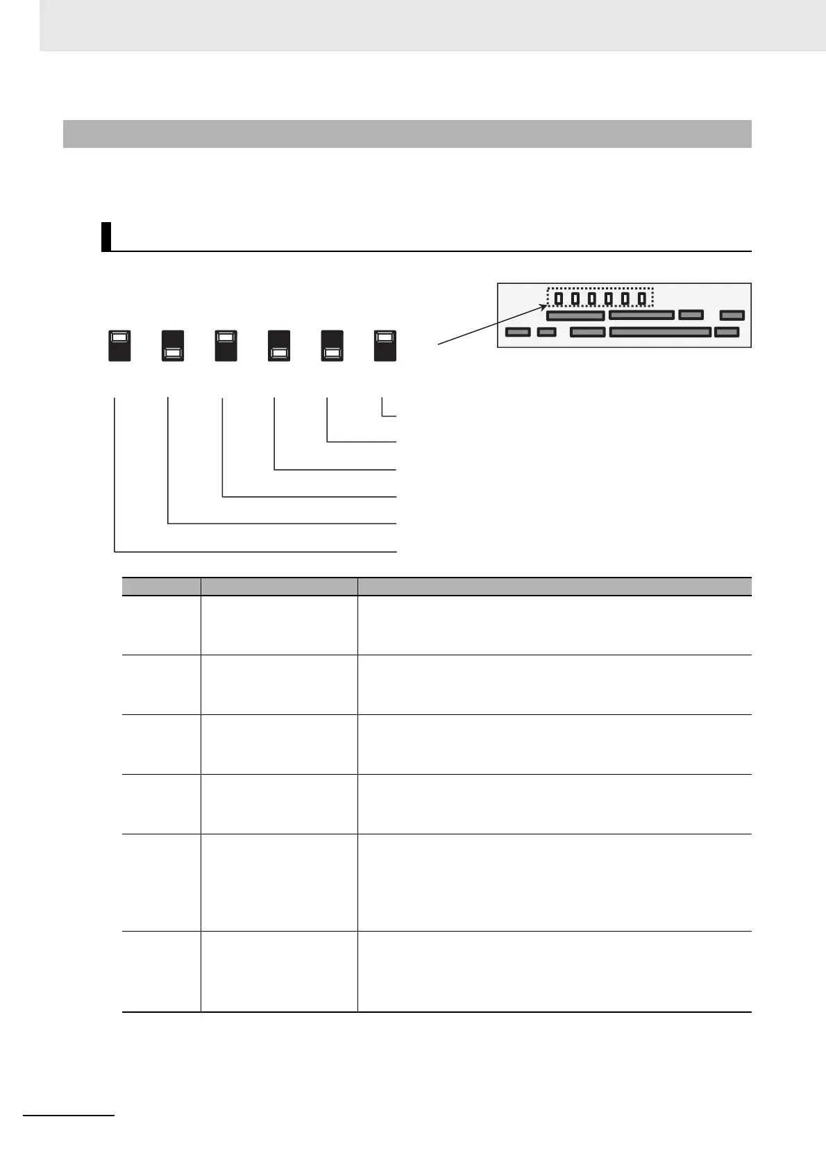
The diagram and table below describe arrangement and function of control circuit terminal block and
switch settings.
2-3-3 Arrangement and Function of Control Circuit Terminal Block
Switch Configurations
Indication SW name Description
Ai1
(SW1)
Analog input 1 switch
Switches input specification of analog input 1 (Ai1 terminal).
10 V: Voltage input is available.
20 mA: Current input is available.
Ai2
(SW2)
Analog input 2 switch
Switches input specification of analog input 2 (Ai2 terminal).
10 V: Voltage input is available.
20 mA: Current input is available.
Ao1
(SW3)
Analog output 1 switch
Switches output specification of analog output 1 (Ao1 terminal).
10 V: Sets to voltage output.
20 mA: Sets to current output.
Ao2
(SW4)
Analog output 2 switch
Switches output specification of analog output 2 (Ao2 terminal).
10 V: Sets to voltage output.
20 mA: Sets to current output.
P.SEL
(SW5)
Switching the method of
power supply to the input
terminals
Switches the method of power supply to the input terminals.
IN: Uses the internal power supply
EX: Uses the external power supply
(In the case of EX, a power supply is required between the input ter-
minals and COM.)
SRC/SINK
(SW6)
Switch of sink/source for
the input terminals
Switches the sink/source logic for input terminals.
This switch is enabled when SW5 is IN.
SINK: Enables sink logic.
SRC: Enables source logic.
SW4
SW3
SW2
SW1
SW5
SW6
10V
20mA
10V
20mA
10V
EX
SINK
SRC
Ao2
Ao1 Ai2
Ai1
P.SEL
(SW4) (SW3) (SW2) (SW1) (SW5) (SW6)
Switch sink/source of the input terminal logic
Switch internal power supply/external power supply of the
input terminal power supply
Switch voltage input/current input of analog input 1
Switch voltage input/current input of analog input 2
Switch voltage output/current output of analog output 1
Switch voltage output/current output of analog output 2
Control circuit terminal area