Appendices B STO Function
B - 8
High-function General-purpose Inverter RX2 Series User’s Manual
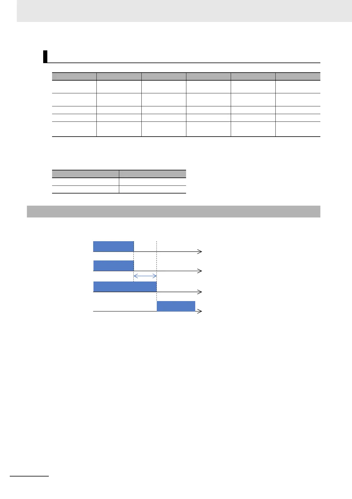
The following shows the timing diagram of output to the motor and output of EDM signals for STO
inputs ST1/ST2.
Signal Matrix
Signal Status 1 Status 2 Status 3 Status 4 Status 5
ST1
*1
*1. The following table shows the correspondence between the input status of ST1/ST2 described in
the table above and status of contact points.
STO
Operation
permitted
STO
Operation
permitted
*2
*2. Regardless of signals for ST1/ST2, the status goes into Status 5 when internal errors are detected.
ST2
*1
STO STO
Operation
permitted
Operation
permitted
*2
Failure detection None None None None Detected
EDM ON OFF OFF OFF OFF
Output to the
motor
Cut off Cut off Cut off Output permitted Cut off
Input status Contact point
STO OFF
Operation permitted ON
B-2-4 Timing Chart
ST1
ST2
EDM
ON
ON
Output
OFF
OFF
ON
OFF
Output to
the motor
10ms or less
cut off