11 Options
11 - 12
High-function General-purpose Inverter RX2 Series User’s Manual
For how to connect regenerative braking unit(s), refer to External Braking Resistor Connection Terminal
(P, RB)/ Regenerative Braking Unit Connection Terminal (P, N) on page 2-55 in this manual.
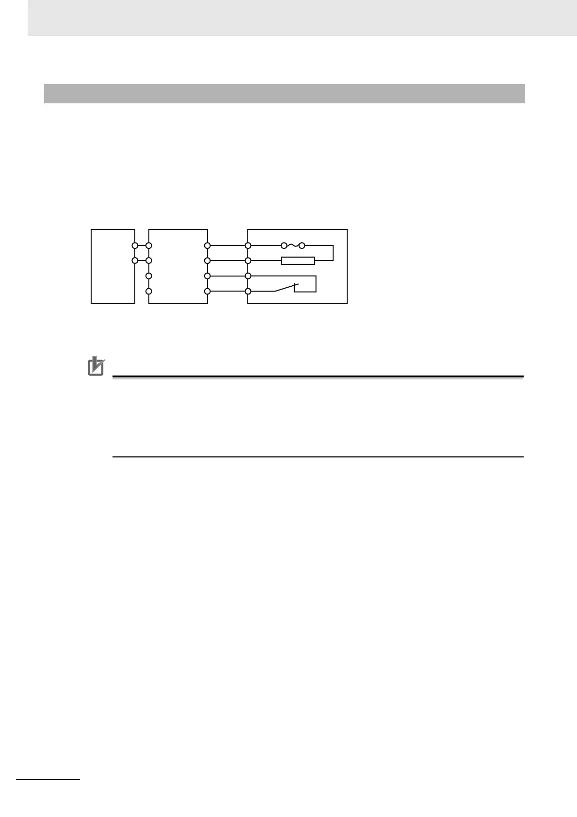
When you desire to shorten a motor deceleration time, use an inverter combined with a braking resistor.
Example of Connection
*1. Alarm output terminal for the regeneration braking unit
When a thermal relay for its built-in resistor or the braking resistor as an option is operated, set a
circuit to shut the power supply of the inverter at the primary side.
Precautions for Correct UsePrecautions for Correct Use
A thermal fuse is built in the braking resistor (RBA, RBB and RBC). After an alarm is issued
from the thermal relay between terminals 1 and 2, overheat may result in a breakage of the
thermal fuse. If the fuse is broken, the braking resistor can’t be restored. Replace the braking
resistor with new one.
Wire the alarm output terminals properly. When thermal abnormality is detected, stop the
inverter operation and cool the braking resistor thoroughly. After that, start the inverter.
11-2-3 Connection Examples
P
N
PB
PB
R1
R2
P
P
1
2
P/+
N/-
AL1:
*1
AL2:
*1
Inverter
Regeneration
Braking Unit
Braking Resistor