2 - 55
2 Design
High-function General-purpose Inverter RX2 Series User’s Manual
2-3 Wiring
2
2-3-4 Wiring for Main Circuit Terminals
When driving a load with a large inertia or a vertical shaft, regenerated energy is fed back to the inverter
when it is decelerating or generating downward movement.
If the amount of regenerative energy exceeds the allowable amount for the inverter, an overvoltage is
detected. Use braking resistors or regenerative braking units to prevent this.
200 V Class Models with 22 kW or Lower/400 V Class Models with 37 kW or
Lower
The models have a built-in regenerative braking circuit.
To improve the braking capacity, connect the optional external braking resistor to these terminals (P,
RB).
• Be sure to install a circuit that detects overheating of the braking resistor via alarm contacts
(thermal relay output terminals) and shuts off the input power supply of the inverter.
• Do not connect a resistor whose resistance is lower than the minimum connection resistance
value specified in the standard specifications table. Doing so may result in damage to the
regenerative braking circuit.
• When using the Braking Resistor (Model: 3G3AX-RBA/RBB/RBC) with a 400-V class
inverter, be sure to connect two braking resistors of the same model in series. Using the
inverter with only one braking resistor connected may cause damage to the braking resistor.
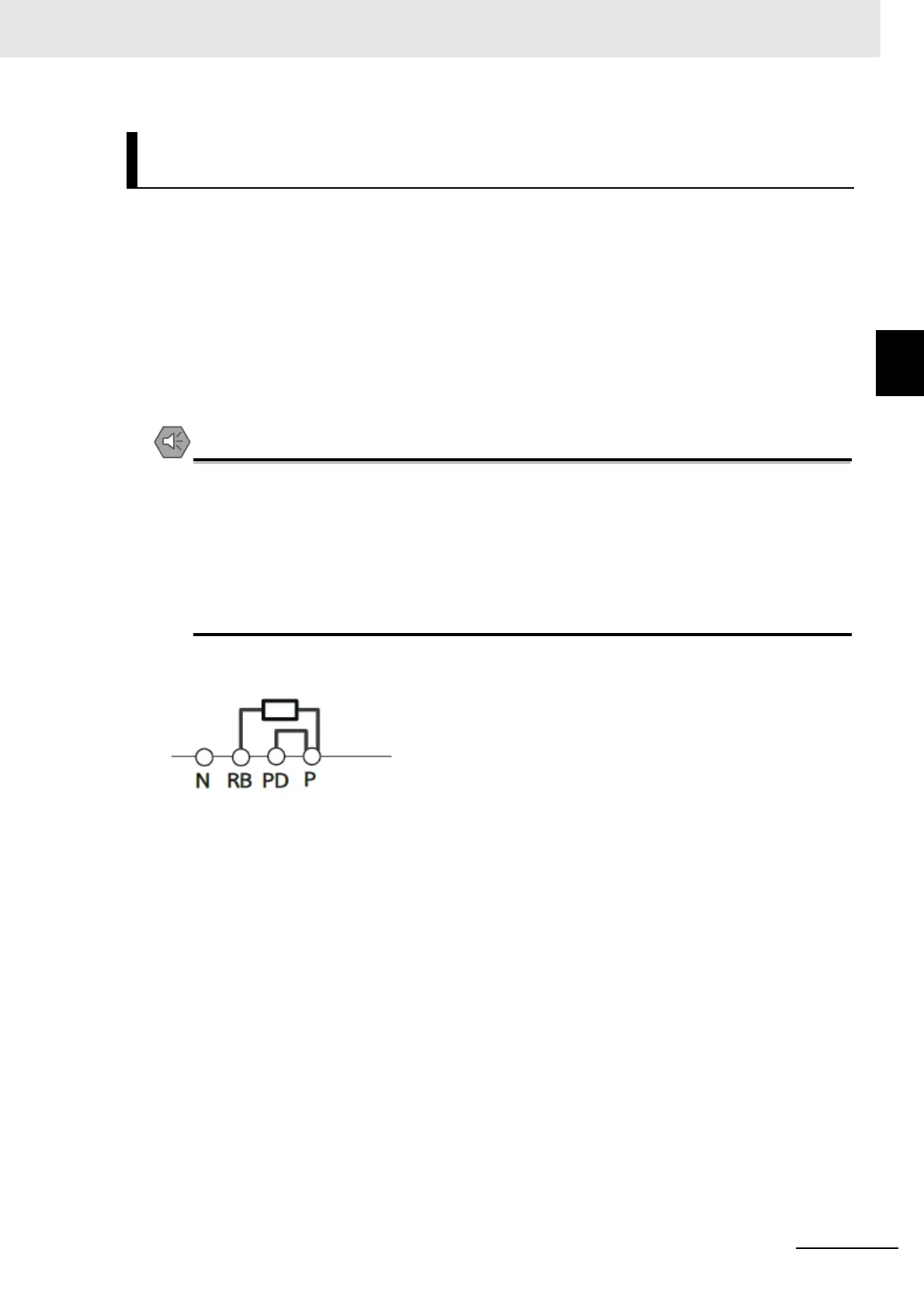
External Braking Resistor Connection Terminal (P, RB)/
Regenerative Braking Unit Connection Terminal (P, N)
Short bar
Braking resistor
(option)