11 - 17
11 Options
High-function General-purpose Inverter RX2 Series User’s Manual
11-4 Regenerative Braking Unit and Braking
Resistor Combination Selection Table
11
11-4 Regenerative Braking Unit and Braking
Resistor Combination Selection Table
Select the combination of the regenerative braking unit(s) and the braking resistor(s) as follows,
according to your inverter.
If the usage rate exceeds 10% ED, or if you need a torque larger than the approximate braking torque,
you need to follow the instruction provided in A-3 Overview of Inverter Selection on page A-25.
• Inverter:
Select the model of your inverter.
The table below assumes that your inverter is used in the heavy load mode and connected to a single
motor with the same capacity.
Make sure that the approximate braking torque in the table shows the assumed value per a motor
with the same capacity at ND mode. When using this inverter at LD or VLD mode, you need to calcu-
late the torque value by dividing VLD by ND.
• Operating conditions:
Show the torque during deceleration and the deceleration time (in % ED) calculated as a percentage
of the cycle time for 1 cycle of operation including the stop time.
• Braking unit/Braking resistor:
Show the required model and number of units.
• Connection form:
Shows the configuration of the regenerative braking unit(s) and braking resistor(s) illustrated in the
connection form table below.
• Restrictions:
Show the maximum deceleration time allowable for the combination shown here and the minimum
resistance that can be connected to the inverter’s built-in regenerative braking circuit or external
regenerative braking unit(s).
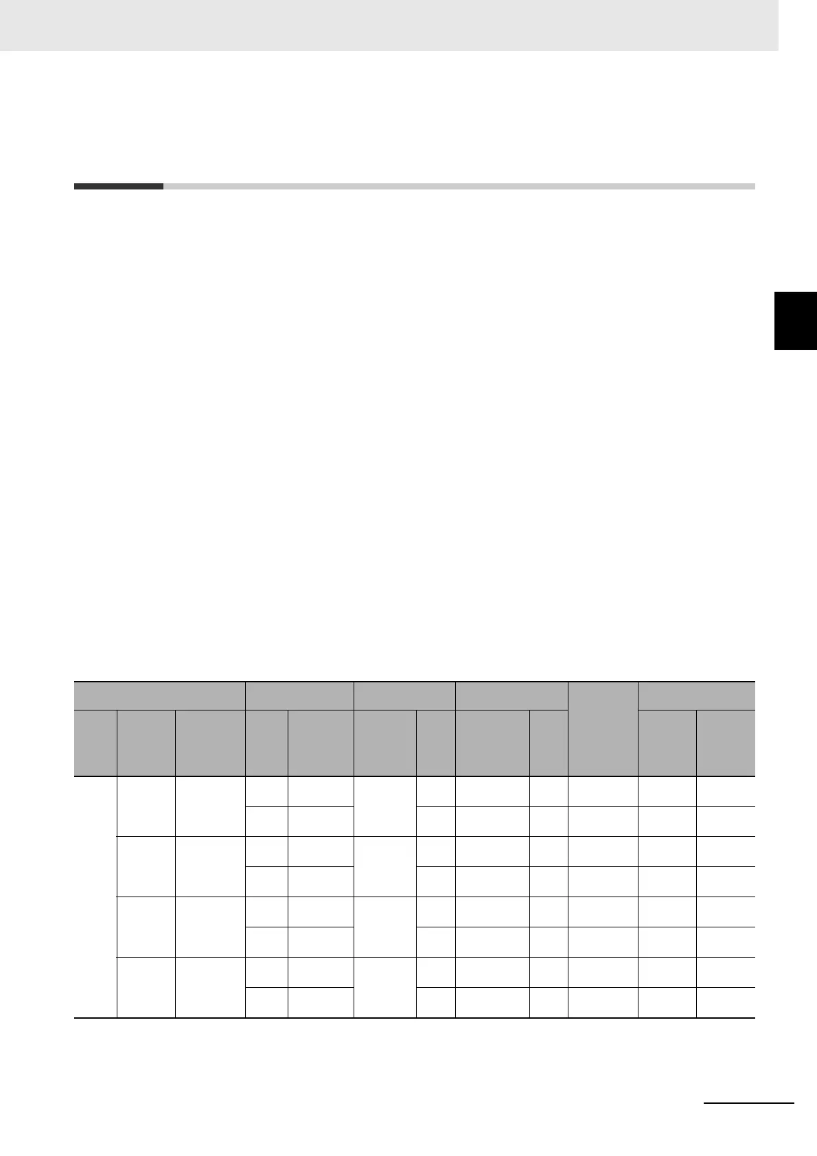
Inverter
Operating condi-
tions
Braking unit Braking resistor
Connection
form
Restrictions
Voltage
class
Max.
applica-
ble motor
capacity
[kW]
Model
%ED
[%]
Approximate
braking
torque [%]
Model
No.
of
units
Model
No.
of
units
Allowable
continu-
ous ON
time [s]
Min. con-
nection
resistance
[
]
200-V
class
0.4
3G3RX2-
A2004
3% 220%
Built into
unit
–
3G3AX-
RBA1201
11 20 50
10.0% 220% –
3G3AX-
RBB2001
11 30 50
0.75
3G3RX2-
A2007
3.0% 120%
Built into
unit
–
3G3AX-
RBA1201
11 20 50
10.0% 120% –
3G3AX-
RBB2001
11 30 50
1.5
3G3RX2-
A2015
2.5% 110%
Built into
unit
–
3G3AX-
RBA1202
11 12 35
10.0% 215% –
3G3AX-
RBC4001
11 10 35
2.2
3G3RX2-
A2022
3.0% 150%
Built into
unit
–
3G3AX-
RBB3001
11 30 35
10.0% 150% –
3G3AX-
RBC4001
11 10 35