8 - 151
8 Applied Settings
High-function General-purpose Inverter RX2 Series User’s Manual
8-9 Applied Output
8
8-9-2 Logical Output Signal
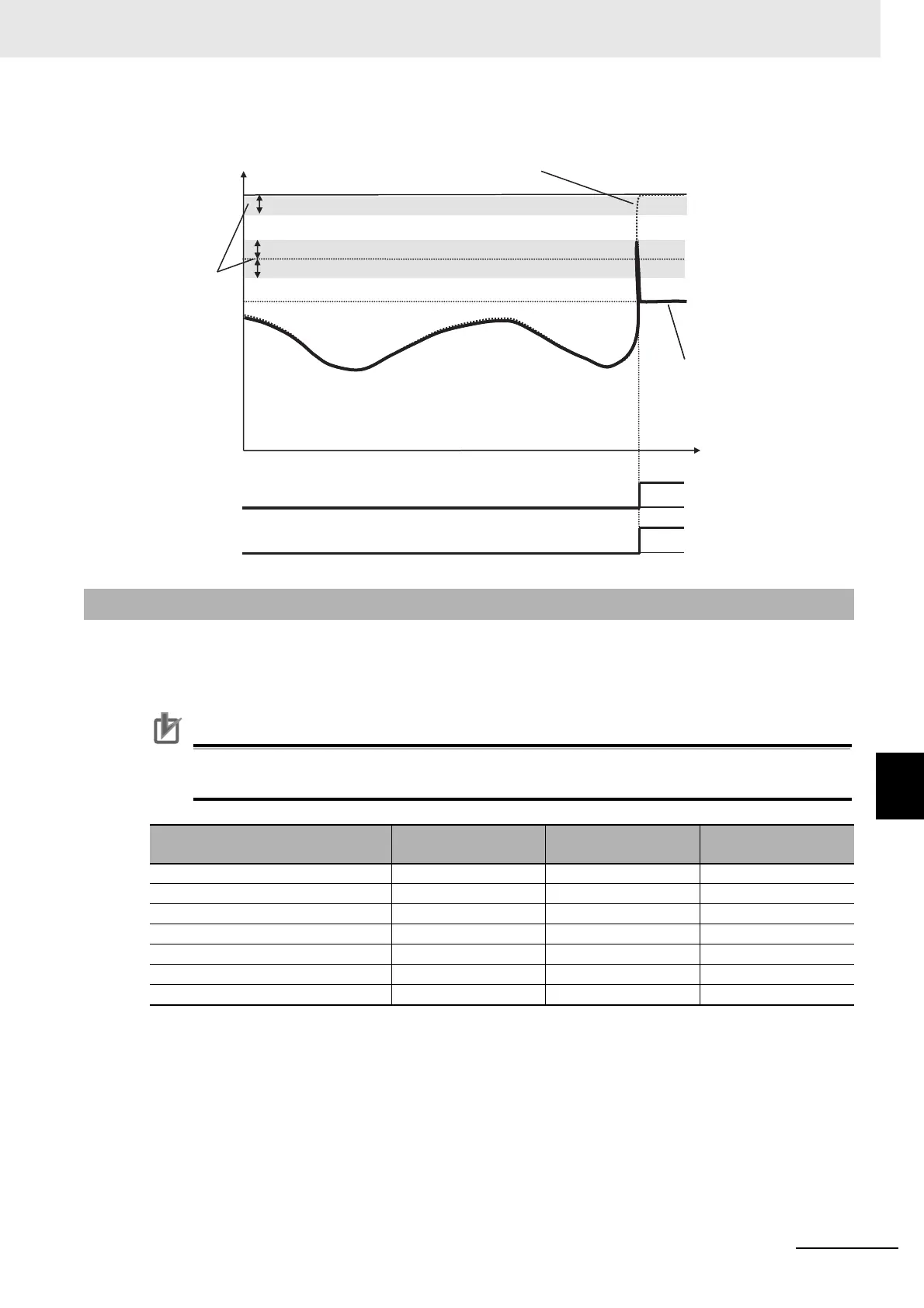
• When the analog input becomes the maximum value (Max) because of a short circuit in the input wire
You can combine the operation of the output terminal function to perform a logical operation for output
signals in the inverter to output various signals.
You can select three types of operators: AND, OR, and XOR.
Precautions for Correct Use
All output signals are subject to operation. However, you are not able to include the results of
logical operations [LOG1] to [LOG7] into the targets of arithmetic operation.
8-9-2 Logical Output Signal
Selected signal
Arithmetic operation
target 1 selection
Arithmetic operation
target 2 selection
Operator selection
068: Logical output signal 1 (LOG1) [CC-40] [CC-41] [CC-42]
069: Logical output signal 2 (LOG2) [CC-43] [CC-44] [CC-45]
070: Logical output signal 3 (LOG3) [CC-46] [CC-47] [CC-48]
071: Logical output signal 4 (LOG4) [CC-49] [CC-50] [CC-51]
072: Logical output signal 5 (LOG5) [CC-52] [CC-53] [CC-54]
073: Logical output signal 6 (LOG6) [CC-55] [CC-56] [CC-57]
074: Logical output signal 7 (LOG7) [CC-58] [CC-59] [CC-60]
Max(100%)
Min(Ai1/Ai2:0%)
(Ai3 :-100%)
[CE-50]/[CE-52]/[CE-54]
[CE-40]/[CE-43]/[CE-46]
[CE-41]/[CE-44]/[CE-47]
[CE-42]/[CE-45]/
[CE-48]
[WCAi1]/[WCAi2]/
[WCAi3]
[Ai1Dc]/[Ai2Dc]/
[Ai3Dc]
Window comparator
upper limit level
Analog input value
Analog operation level
in abnormal conditions
Ai1/Ai2/Ai3 inputs
Hysteresis width
A short circuit
occurred↓
Analog adopted value
Window comparator
lower limit level

 Loading...


